Welding Seam Cracks in Main Steam Pipe Valves
Jul 10, 2024
On this page
The steam generated by the power plant boiler has high pressure, high temperature, and significant volume, resulting in considerable safety hazards. Since multiple power plant boilers share one main pipe, to ensure safety and reliability during operation, the main steam pipe before each boiler is merged into the main pipe and is generally isolated from the main pipe by a segmented valve. The segmented valve consists of two cut-off valves in series, which is more convenient for later inspection and maintenance, and can also prevent the need for inspection of a single power plant boiler due to internal leakage. When the power plant boiler is operating normally, the cut-off valve is open, and the high-temperature, high-pressure steam generated is sent to the user through the main pipe. When a boiler has an accident or needs sectional inspection and maintenance, the two shut-off valves can be closed to stop the affected section. This ensures the normal operation of the section being inspected and maintained while allowing other adjacent boilers to continue operating normally. The pipeline structure of the main pipe-controlled power station boiler is relatively simple during installation. Generally, both ends of the main pipe lead to the steam turbine, and the middle receives steam generated by the boiler, providing high economic benefits. However, for power station boilers operated by the main pipe, it is difficult to conduct regular inspections or to inspect and maintain the main pipe if there are problems. Multiple power station boilers need to be shut down simultaneously before corresponding operations can be carried out. Therefore, this leads to inflexible operation scheduling. If any valve on the main pipe malfunctions, the equipment connected to the main pipe must stop running. Additionally, the operating pressure, temperature, and other parameters of all power station boilers and steam turbines connected to the main pipe must be the same.
Entrusted by a chemical plant, a regular inspection was conducted on the pipeline from the main steam pipe of its power workshop to the #3 turbine. The pipeline has a design pressure of 8.89 MPa and a design temperature of 510°C. The main pipe is made from 12Cr1MoVG, and the pipeline has a size of 273 × 25 mm. It was put into use in June 2010 and had been in operation for about 88,000 hours by the time of inspection. The valve body material in the pipeline is ZG20CrMoV.
Entrusted by a chemical plant, a regular inspection was conducted on the pipeline from the main steam pipe of its power workshop to the #3 turbine. The pipeline has a design pressure of 8.89 MPa and a design temperature of 510°C. The main pipe is made from 12Cr1MoVG, and the pipeline has a size of 273 × 25 mm. It was put into use in June 2010 and had been in operation for about 88,000 hours by the time of inspection. The valve body material in the pipeline is ZG20CrMoV.
Analyzing the morphological characteristics of the cracks combined with construction documents reveals the causes of the cracks. The detected crack is located on the fusion line near the junction of the parent material and the welding seam on the valve body side, exhibiting characteristics of cold cracks. Data consultation reveals that the valve body is made from ZG20CrMoV, which has low thermal conductivity and a large thermal expansion coefficient. The thermal cycle of welding causes large residual stress, and the cooling rate requirements for post-weld heat treatment are stringent, easily causing uneven structure and performance in the casting. When welding ZG20CrMoV and 12Cr1MoV, hardened structures easily form near the welding seams. When the welded joint is tempered at a high temperature, its strength, plasticity, and structural stability are difficult to control, increasing the likelihood of cold cracks forming at the welding seam.
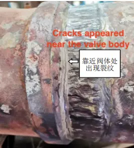
2) Figure 1 shows that the thickness of the valve side wall is significantly different from that of the steel pipe side wall. An angle of about 90° forms between the welding seam surface and the valve parent material, resulting in structural discontinuity and stress concentration, making the fusion line of the welded joint the weakest link.

Figure 1 Cracks at the valve body
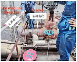
3) The welding seam crack appears in the 1/2 circle on the west side of the welding seam (as shown in Figure 2). Figure 1 shows that the crack is wider at the lower part due west. Therefore, it is inferred that this area is subject to a larger oblique upward force, which is the starting point of the crack. The pipeline medium flows from west to east, with many elbows in front of the valve. As the steam medium flows through this area, the direction changes frequently, producing a large oblique upward torque on the cracked welding seam in front of the valve. Therefore, fatigue microcracks form during long-term operation. During pipeline shutdowns or due to improper control of the cooling rate, the microcracks can expand. Since the factory initially planned to cut the welding seam and re-weld it, the initial fracture morphology was destroyed when the repair plan changed to pipe replacement. Therefore, the pipe was not cut for welding seam fracture morphology analysis.

4) Inclusions in the welding seam destroy the uniformity and continuity of the base metal, reducing its bearing area, easily producing stress concentration, and forming a fatigue crack source. During operation, the valve inlet pipe expands and breaks in the circumferential direction of the pipe wall.
2) Figure 1 shows that the thickness of the valve side wall is significantly different from that of the steel pipe side wall. An angle of about 90° forms between the welding seam surface and the valve parent material, resulting in structural discontinuity and stress concentration, making the fusion line of the welded joint the weakest link.

Figure 1 Cracks at the valve body
3) The welding seam crack appears in the 1/2 circle on the west side of the welding seam (as shown in Figure 2). Figure 1 shows that the crack is wider at the lower part due west. Therefore, it is inferred that this area is subject to a larger oblique upward force, which is the starting point of the crack. The pipeline medium flows from west to east, with many elbows in front of the valve. As the steam medium flows through this area, the direction changes frequently, producing a large oblique upward torque on the cracked welding seam in front of the valve. Therefore, fatigue microcracks form during long-term operation. During pipeline shutdowns or due to improper control of the cooling rate, the microcracks can expand. Since the factory initially planned to cut the welding seam and re-weld it, the initial fracture morphology was destroyed when the repair plan changed to pipe replacement. Therefore, the pipe was not cut for welding seam fracture morphology analysis.

4) Inclusions in the welding seam destroy the uniformity and continuity of the base metal, reducing its bearing area, easily producing stress concentration, and forming a fatigue crack source. During operation, the valve inlet pipe expands and breaks in the circumferential direction of the pipe wall.
To ensure the system could be put into operation quickly, the initial plan was to use oxygen-acetylene flame gouging and then grind it with a grinder to eliminate the cracks. However, during the implementation of this plan, it was found that the gap after grinding with the grinder was very small, making it difficult to confirm whether the defects were completely eliminated by non-destructive testing. To ensure the quality of the weld seam, the factory decided to cut and replace the cracked weld seam and its south side short section. The treatment plan is as follows:
1) If the south side short section continues to be used, the tensile strength, hardness, and other mechanical properties of the parent material will decrease due to the secondary heating during the second welding. Therefore, it is recommended that the factory use a new pipe of the same material and specification. Before installation, our unit measured the wall thickness and conducted spectral analysis of the used pipes, which all met the relevant regulations.
2) There is a disadvantage of unequal thickness at the connection end of the valve and the straight pipe. Therefore, when welding alloy steel pipes, it is necessary to prioritize welding this unequal thickness weld to avoid making it an installation weld, which would cause stress concentration during assembly or welding, resulting in defects in this part. During construction, the weld and the inner surface of the pipe are cleaned before each During construction, the weld and the inner surface of the pipe are cleaned before each weld group is matched, and each weld group is prefabricated to ensure it is not affected by external forces. When welding, strictly implement preheating and control the interlayer temperature according to the procedure documents and specifications to prevent the tendency of cold cracks.
3) After completing the argon arc welding base and manual cover welding process, the appearance quality inspection is carried out immediately after passing the post-weld heat treatment. According to GB/T 30583-2014 "Post-weld Heat Treatment Regulations for Pressure Equipment" and GB/T 20801-2006 "Pressure Pipe Specifications Industrial Pipelines," crawler ceramic electric heaters are used to perform winding heat treatment on welding seams, heat-affected zones, and adjacent parent materials. The heating width of the heat treatment is not less than three times the pipe wall thickness on each side, and not less than 60 mm from the center of the welding seam. The insulation width is not less than five times the pipe wall thickness on each side from the center of the welding seam to reduce the temperature gradient. The heating and cooling speeds are controlled at 220℃/h. The temperature is first freely raised to 300℃, then raised to 720℃ at a heating rate of 220℃/h. After two hours of insulation, the temperature is cooled. During the cooling process, the temperature below 300℃ can no longer be controlled. When the temperature drops to 100℃, the insulation cotton, ceramic electric heater, and thermocouple can be removed. After heat treatment, the alloy steel pipeline is subjected to a hardness test. Its hardness value shall not exceed the Brinell hardness of the parent material plus 100, and HB shall not be greater than 270. The 12Cr1MoVG pipeline is a low-alloy steel, and delayed cracks are prone to occur during welding. According to the provisions of GB/T 20801-2020 "Pressure Pipe Specification Industrial Pipe," the welded joints of materials with a tendency for delayed cracking shall be subjected to non-destructive testing 24 hours after welding.
The pipelines within the boiler range have been operating under high temperature and high pressure conditions, which are the focus and difficulty of control. Based on the possible causes of valve weld seam cracks, the following suggestions are put forward to prevent similar problems in the future and ensure the safe operation of the pipeline:
Arrange the order of welding in a reasonable and planned manner, so that welds of unequal thickness weldments, similar to valves, are prefabricated on the ground first. This prevents the installation welds of the pipeline from being placed at locations with unequal thickness weldments.
When welding the pipeline, avoid misaligned joints that may cause weld cracks. Effective measures should be taken to ensure that the weld joints are not affected by external forces, and welding quality should be strictly controlled to avoid stress concentration and structural discontinuity.
To reduce and avoid the occurrence of cracks, low-alloy steel materials generally require effective preheating before welding and post-weld heat treatment. Before welding the pipeline, a welding procedure should be prepared based on the welding procedure assessment report (or the pre-welding procedure that has passed the technical review) to guide welders in welding and post-weld heat treatment. Welding materials that meet the requirements of the design documents and relevant standards should be selected and dried. After the groove preparation is completed, the weldment should be strictly preheated, the temperature between each layer of welds should be controlled during welding, and heat treatment should be performed immediately after welding.
During regular inspection and maintenance of the main steam pipeline and mother pipe of the power plant, the user unit should strictly implement the process requirements for start-up and shutdown, and it is strictly forbidden to quickly cool down by passing instrument air. The pipeline within the boiler range should be measured at fixed points with a high-temperature thickness gauge to determine the annual corrosion rate. Additionally, thickness measurement at unfixed points should be carried out to investigate the corrosion of each pipe fitting in the pipeline promptly, collecting and organizing relevant information on the overall and local corrosion of the pipeline.
Rationally formulate a pipeline purge plan, remove impurities from the pipeline promptly, and ensure regular maintenance of the auxiliary devices on the pipeline, such as pipeline supports and hangers, creep measurement points, etc.
Based on the results of regular inspections and the operation time of the pipeline, the regular inspection cycle should be reasonably determined. A detailed inspection plan should be formulated during regular inspections, including creep, hardness, and metallographic tests. Pay attention to changes in hardness values and the spheroidization state of metallographic structures, keep records, and regularly compare the data before and after. For pipelines with severe spheroidization levels and obvious reductions in hardness values, segment mechanical performance analysis should be carried out if necessary to ensure safe and long-term operation of pipelines within the boiler range.
Previous: Intelligent, Standardized and Energy-saving Control Valves In Industrial Control
Next: Selecting Control Valves for Offshore Oil and Gas Fields


