Troubleshooting of Pneumatic Quick-Closing Ball Valves
Apr 05, 2025
During the operation of long-distance liquid pipelines in aerospace liquid rocket engine test benches, various factors may lead to failures. A pneumatic valve failure can compromise liquid transportation stability and disrupt real-time pressure and flow regulation. Compared to traditional manual valves, pneumatic quick-closing ball valves provide easier control, greater reliability, and a faster response. This paper analyzes a real-world case involving the long-distance liquid pipeline of an aerospace liquid rocket engine test bench. By analyzing the structure and characteristics of the pneumatic quick-closing ball valve, this study identifies and investigates an issue where the PTFE valve seat ring is unexpectedly sheared off and enters the filter in the liquid pipeline during operation. Specific solutions are then proposed. After verification and optimization, the pneumatic quick-closing ball valve meets the test requirements.
With the continuous advancement of industrial production, pneumatic quick-closing ball valves have become essential control components in industrial pipeline systems, playing a crucial role in their automation. However, China has lagged behind other countries in the development of intelligent instrumentation and control technology, with limited investment in valve control technology yielding minimal results. Pneumatic quick-closing ball valves have several advantages over standard ball valves, including low fluid resistance, a long service life, high reliability, and superior sealing performance. As a result, they are widely used in aerospace rocket engine test systems. However, under actual operating conditions, failures of the ball valve or sealing components, especially in high-pressure environments, can lead to medium leakage and serious incidents such as fires, pipeline explosions, or other safety hazards.
Pipeline valve failure remains a significant issue in practical engineering applications, influenced by factors such as the management levels of production, construction, and operational stakeholders. Studies have shown that valve seal failures can occur during transportation, installation, commissioning, operation, and maintenance. Effective quality control, maintenance, and supervision during the production, construction, and commissioning phases are therefore critical. With the progress of liquid rocket engine development in China, the frequency of test system use has increased. In practical applications, it was observed that the seat ring of the pneumatic quick-closing ball valve was severed, causing the valve seal to fail. This failure compromised both the test system's quality and safe operation, as well as the evaluation of engine performance and parameters. In severe cases, this can result in engine damage and potential casualties. This paper analyzes the causes of pneumatic ball valve failure in liquid rocket engine test propellant systems and proposes appropriate solutions.
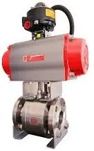
The ball valve mainly comprises pressure-bearing components (including the valve body and side valve body), pressure-regulating components (such as the ball and valve seat), and additional accessories. Pneumatic fast-closing valves utilize cylinders as actuators, using compressed gas to drive the valve and generate the power required for operation. The pneumatic valve is composed of three primary components: the pneumatic actuator, valve body, and accessories, as shown in Figure 1. The actuator comprises components including springs, diaphragms or pistons, pneumatic rods, and handwheels. It operates using clean compressed air as a power source, receives gas signals (20–100 kPa) or electrical signals (4–20 mA), and drives the valve body to adjust the flow area between the valve core and valve seat, thereby controlling the flow. The valve body primarily comprises the valve disc, valve cage, valve stem, valve seat, valve cage pressure ring, and additional components. Accessories include the solenoid valve, air source triplex, limit switch, positioner, and control box. Pneumatic ball valves require pneumatic actuators for operation, with an actuation time of 0.05 seconds per cycle. They support both on-site and remote centralized control, minimizing the risks of manual operation in high-altitude and specialized environments. This improves efficiency, reduces labor requirements, and enhances operational safety.
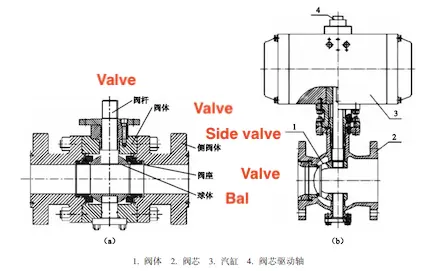
1. Valve body 2. Valve core 3. Cylinder 4. Valve core drive shaft
(a) Ball valve structure (b) Composition of pneumatic ball valve
Figure 1 Structural composition of pneumatic ball valves
Overall, pneumatic ball valves have evolved from globe valves. The working principle of pneumatic valves is as follows: when a pressure signal of 0.02–0.10 MPa is applied to the regulator chamber, the diaphragm generates thrust, compressing the spring as the thrust plate moves downward. This action drives the valve stem, push rod, and valve core downward, regulating the valve opening and adjusting flow, thereby enabling process automation.
In summary, pneumatic valves offer the following advantages:
- Pneumatic valves offer fast response times, executing adjustment commands swiftly.
- Pneumatic valves can be equipped with large cylinders to produce high torque.
- Pneumatic valves ensure long-term safe and reliable operation, even in harsh environments.
Key features of pneumatic ball valves include a compact design, remote control capability, lightweight actuation, small size with large diameter options, reliable sealing, simple structure, easy maintenance, precise sealing surface alignment with the ball, and resistance to medium-induced erosion. They are suitable for general media such as water, solvents, acids, and natural gas, as well as specialized media like oxygen, hydrogen peroxide, methane, and ethylene.
During a routine inspection of the filter on a long liquid propellant delivery pipeline, excess material was found, affecting the medium's delivery efficiency. Upon disassembling the filter, it was determined that the excess material was a white, curved strip of plastic, as shown in Figure 2.
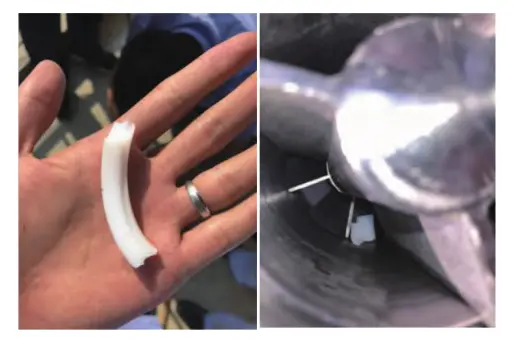
Figure 2: The excess material
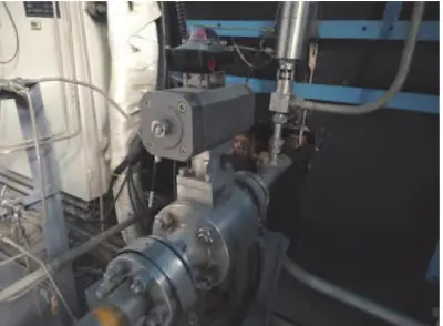
Based on its appearance and composition, it was determined that the excess material was likely a cut-off PTFE valve seat ring from the ball valve in the pipeline. Upon further disassembly, it was confirmed that the excess material was a cut-off valve seat ring from the DN80-PN63 pneumatic quick-opening ball valve, which had been displaced into the filter. This was caused by the failure of the valve seat ring, which led to leakage in the pneumatic quick-closing ball valve during extended use. Figure 3 shows the faulty valve on-site.
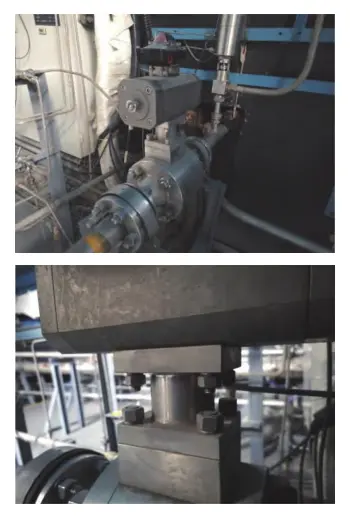
Figure 3: The faulty valve
As shown in the ball valve switching process in Figure 4 and the sealing surface scraping diagram in Figure 5, sliding friction between the valve seat and limit pin, as well as between the wedge surface and ball pin, determines the contact area and deformation conditions at these points.
These are influenced by both the normal load and tangential force. The failure occurred during the valve's operation when the ball's sealing surface scraped the interfering component, causing the valve seat ring to become dislodged and subsequently severed by the ball. The dislodged ring then entered the filter through the pipeline at the valve's outlet.

Figure 4: Opening and closing of ball valves
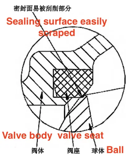
Figure 5 Ball valve sealing surface scraping
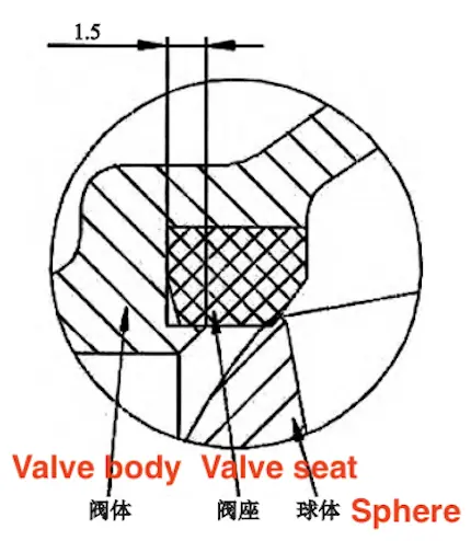
Figure 6 Design depth of fire step for faulty valve
The primary reasons for the valve seat ring being scraped by the ball's sealing surface are as follows:
The fire-step design of the faulty valve is too shallow. As shown in Figure 6, the measured depth of the fire step is 1.5 mm. The valve seat ring typically has a thickness of 1.5–2 mm, making it susceptible to being squeezed out and preventing it from effectively securing or protecting the valve seat ring.
During the processing and inspection of the faulty valve body, the dimensions of the valve seat groove exceeded the design tolerance. The specified tolerance range is +0.1 mm to 0 mm, whereas the actual measured dimensions ranged from +0.35 mm to +0.2 mm. This deviation resulted in a significant gap between the valve seat ring and the valve body. The design dimensions of the valve seat groove are shown in Figure 7.
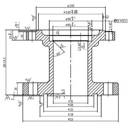
Figure 7: Dimensions of Valve Seat Grooves
The purchased ball may not have been manufactured according to the design specifications. Figure 8 shows the design dimensions of the ball's chamfer in the faulty valve, which is too small and sharp. The valve is equipped with a 5.5 MPa high-pressure pneumatic actuator, resulting in rapid opening and closing. The combination of the sharp chamfer and fast opening and closing causes the sealing ring to be scraped off and severed by the ball.
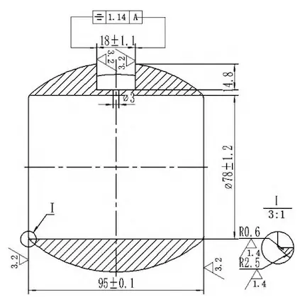
Figure 8: Chamfer Dimensions of the Ball in the Faulty Valve
The floating ball valve consists of a spherical closure element with a central through-hole that matches the pipeline’s diameter. The inlet (left valve body) and outlet (right valve body) each house a PTFE valve seat ring within a metal valve body. When the ball’s through-hole aligns with the pipeline, the valve is open; when perpendicular, it is closed. The valve rotates 90° to open or close. Figure 9 provides a schematic of the floating ball valve structure. When the valve is closed, inlet pressure pushes the ball against the valve seat ring at the outlet, generating contact stress on the sealing surface and forming a sealing contact zone. The contact stress per unit area in this zone is known as the valve’s sealing pressure ratio. Effective sealing is achieved when the sealing pressure ratio exceeds the minimum required for proper sealing. Figure 10 illustrates the sealing principle of a floating ball valve. As shown in Figure 11, the sealing principle of the floating ball valve dictates that higher medium pressure increases the sealing pressure ratio, improving sealing performance. However, at low pressures, the force exerted by the medium on the ball may be insufficient to achieve the necessary sealing pressure ratio. To address this, an interference fit is designed between the valve seat sealing surface and the ball, generating a preload force that contributes to the sealing pressure ratio, ensuring effective sealing even at low pressures.
The seat ring and ball of a floating ball valve must be preloaded with a specific interference fit to ensure sealing performance at low pressure. However, because the seat ring does not elastically retract during operation, misalignment between the ball's edge and the seat ring during opening and closing may cause abrasion to the sealing surface. If the gap between the seat ring and the valve body is too large or the fire-step is too shallow, the seat ring may not be securely held in place. During valve operation, the ball's edge may scrape material from the seat ring. Additionally, during rapid valve actuation, a sharp chamfer on the ball's edge can exacerbate the cutting of the seat ring.
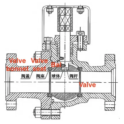
Figure 9 Common floating ball valve structure
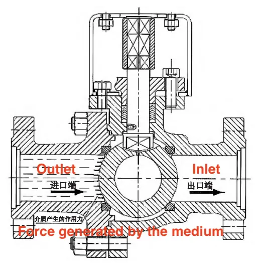
Figure 10 Sealing principle of floating ball valves
For reason (1), the fire step of the faulty valve is too shallow to securely hold and protect the seat ring. It is repaired using a welding rod compatible with the valve body material, and its depth is re-machined from 1.5 mm to 3 mm. Figure 12 shows a schematic of the fire step depth. For the faulty valve described in reason (2), the dimensions of the valve seat hole exceeded the design tolerance during processing and inspection, resulting in a significant gap between the valve seat ring and the valve body. The proposed solution is to measure the outer diameter of the valve seat hole on the actual valve body, use a qualified PTFE rod to rematch the valve seat ring, and reduce the gap between the valve seat ring and the valve body. Figure 13 illustrates the process of matching the valve seat ring.
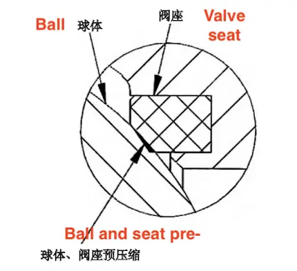
Figure 11 Design principle of floating ball valve seats
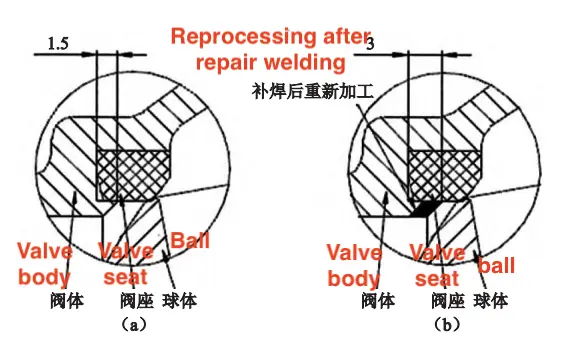
(a) Before inspection and modification (b) After inspection and modification
Figure 12 Correction of fire step depth
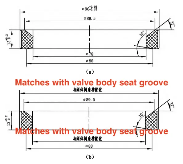
Figure 13 The matching valve seat ring size
For the faulty valve in reason (3), a 5.5 MPa high-pressure pneumatic actuator is used, causing rapid valve actuation that generates significant stress and shear forces on the friction surface, leading to the sealing ring being scraped and severed by the ball. The proposed solution is to measure the chamfer size of the ball. If the chamfer does not conform to the design specifications, a new ball that meets the requirements should be procured.
Based on the identified cause of the valve failure, the ongoing products and their corresponding design drawings were reviewed to confirm that the fireproof platform depth adequately protects the valve seat ring from being scraped out of the valve seat groove by the ball. Furthermore, workshop personnel and quality control staff received training on proper processing and measurement techniques for the valve body’s seat groove, with a focus on the importance of following design specifications. Each product in the workshop was inspected, and any out-of-tolerance dimensions were corrected by adjusting the valve seat ring. Additionally, the quality control department was directed to use specialized tools to measure the chamfer size of the balls in the warehouse. It was found that some ball chamfers did not conform to the design specifications. These non-conforming spheres were returned to the manufacturer for rework according to the design specifications. The modified valve was then tested by introducing nitrogen to raise the internal pressure to 5.5 MPa, maintaining this pressure for 10 minutes, during which no leakage occurred. The valve was then reconnected to the test system and successfully completed the 2500-cycle life test, demonstrating excellent sealing performance and meeting the product’s sealing requirements.
During a routine inspection of the filter on the propellant medium delivery pipeline of a liquid rocket test bench, excess material was found. The material was identified as the valve seat ring from the DN80-PN63 pneumatic fast-closing ball valve, which had been sheared off by the ball and entered the filter through the valve's outlet. An analysis of the valve’s structure, production drawings, and actual part dimensions revealed that the failure was due to an excessive gap between the valve seat ring and the valve body, as well as a shallow fire step, which led to inadequate fixation and protection of the valve seat ring. Additionally, the rapid opening and closing action of the pneumatic valve generated significant instantaneous stress and shear forces. The chamfer size of the ball mouth on the purchased ball should be strictly verified against the design specifications. After adjustments and optimization, the ball valve exhibited reliable sealing in the test system, with normal operation and excellent performance, ensuring the stable and reliable functioning of the test system.
Previous: Flow Field Characteristics and Erosion Mechanisms in Ball Valves with Various Seat Structures
Next: Finite Element Analysis of Titanium Floating Ball Valve Seats

