The Structure of A Common Eccentric Metal Seated Butterfly Valve
Aug 27, 2024
On this page
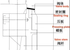
The structure of a common eccentric metal-seated butterfly valve, shown in Figure 1, mainly consists of a valve body, butterfly plate, sealing ring (generally made from directly processed or multi-layered stainless steel parts), sealing plate, valve stem, and fasteners.

Figure 1 The structure of a common eccentric metal seated butterfly valve
Technical points analysis: The most common eccentric metal-seated butterfly valves are mainly divided into two types: double-eccentric and triple-eccentric structures. Although four-eccentric or five-eccentric metal-seated butterfly valves are mentioned in various promotional and introductory materials, they are all derived from the three-eccentric design. The sealing surface processing of this butterfly valve utilizes special tooling, employing the principle of eccentric structure, to rotate and turn out an oblique conical sealing surface, with each cross-section differing. When the butterfly plate is closed, the oblique conical sealing surface gradually fits from the upper and lower shaft hole positions to the three o'clock and nine o'clock positions. The eccentricity of the shaft hole (valve stem position) drives the butterfly plate to compensate to a certain extent, establishing an initial seal. Theoretically, there is almost no interference fit between the sealing ring on the butterfly plate and the sealing surface of the valve seat, which can be verified by 3D modeling. However, in actual production and assembly, most workers default to a certain interference amount to achieve forced sealing. Some manufacturers also further tighten the actuator based on the actual leakage during the sealing pressure test after assembling the metal-seated butterfly valve. This helps achieve interference-fit sealing.
Although in most cases, the leakage of the valve can be temporarily solved by the above method for normal temperature working conditions, under low or even ultra-low temperature working conditions, all parts will be affected by thermal expansion and contraction and will be deformed to varying degrees, particularly at the key positions of the sealing ring and the valve body sealing surface. The structure of the oblique cone surface will be affected by factors such as irregular shape or uneven wall thickness, leading to different shrinkage directions and amounts. Therefore, it is difficult to meet the sealing grade requirements of BS6364 using the common compensation methods mentioned above, and even more challenging to meet the performance requirements of MESC SPE 77-200 Shell for ultra-low temperature valves under low temperatures.
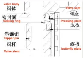
As shown in Figure 2, the structure of a metal-seated butterfly valve with a movable, replaceable valve seat is mainly composed of a valve body, a sealing ring (generally made of stainless steel and processed or bonded in multiple layers), a sealing pressure plate, a valve stem, a tapered pin (some companies use cylindrical pins), a butterfly plate, a movable valve seat, and fasteners.

Figure 2 Structure of a metal seated butterfly valve with a movable replaceable valve seat
Technical Point Analysis: Given the difficulty in maintaining valves with BW (welded end), a sealing structure with a replaceable valve seat has been developed based on conventional eccentric metal-seated butterfly valves. The butterfly plate, sealing pressure plate, and sealing ring of this metal-seated butterfly valve with a replaceable valve seat are not significantly different from those of conventional structures. The metal valve seat and valve body are split structures, which is equivalent to separating the valve seat from the valve body in conventional designs. A metal gasket is typically used to create a seal between the split valve seat and the valve body. A multi-open ring is positioned behind the split valve seat. The screws and the multi-open ring are threaded and pass through threaded holes to the back of the movable valve seat. By fully tightening the screws, an effective seal is created between the movable valve seat and the valve body. This is typically a static seal, and no damage is expected to occur.
When the seal between the valve seat and the sealing ring leaks due to dynamic wear or other reasons, the reserved maintenance manhole can be opened, the screws can be removed, and the multi-open ring can be taken out to replace core components such as the movable valve seat or the sealing ring. Compared with the conventional body-type sealing form, this structure offers certain advantages in terms of maintenance time and cost, but the overall opening and closing method and sealing principle remain unchanged. During each closure, the sealing ring and the valve seat sealing surface must still undergo some wear and interference to achieve the sealing effect, which impacts the product’s service life, especially in medium cut-off positions with frequent switching. This issue is particularly pronounced.
Previous: The Use and Selection of Control Valves
Next: New Ultra-Low Temperature Zero Friction Seal Compensation Butterfly Valves


