Simulation Analysis of Cryogenic Ball Valve Based on Thermo-Solid Coupling
Feb 06, 2025
Ball valves are key control components widely used in industries such as petrochemical and aerospace. The cryogenic ball valve is vital in the paraxylene production process, where it handles a low-temperature solid-liquid two-phase mixture. Given the demanding operating conditions, it is essential to validate the valve’s reliability. This study investigates the cryogenic ball valve used in the paraxylene process. A 3D model is developed, and computational fluid dynamics (CFD) is applied to analyze the temperature field, stress distribution, and deformation of the valve components under standard operating conditions (-67°C, 7.5 MPa). The analysis confirms that the stress on each valve component remains within the material's allowable limits. Additionally, the lowest temperature at the packing exceeds the required 0°C, confirming the valve’s reliability under cryogenic conditions. This study contributes to the understanding of thermo-solid coupling analysis in cryogenic valves.
Para-xylene is a key raw material in chemical manufacturing, used in the production of products such as polyester fibers, resins, coatings, and pesticides. The most advanced method for producing para-xylene is the two-stage reslurry crystallization process, which operates entirely at low temperatures. Cryogenic ball valves are crucial in this process. Due to the low operating temperature, high internal pressure, and challenging conditions, any failure in the valve components could pose significant risks. Therefore, analyzing the temperature and stress fields of the cryogenic ball valve under operating conditions is essential.
Current research on cryogenic valves primarily focuses on ultra-low-temperature ball valves for liquefied natural gas (LNG). Most studies concentrate on valve structural design and sealing pressure ratios, with limited focus on comprehensive stress field analysis. This study conducts a thermo-solid coupling simulation of the cryogenic ball valve used in the para-xylene process, analyzing its temperature field, stress field, and deformation under low-temperature conditions to validate its reliability.
The valve body structure is simplified based on finite element analysis requirements. Since the handle and threaded holes in non-critical areas have minimal impact on stress analysis, they are excluded. The simplified valve body model is depicted in Figure 1. The meshing feature in ANSYS Workbench is applied to discretize the calculation domain, and a polyhedral mesh is used to refine the mesh around smaller seals. The results are displayed in Figure 2.
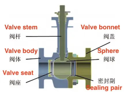
Figure 1 Simplified model of ball valve
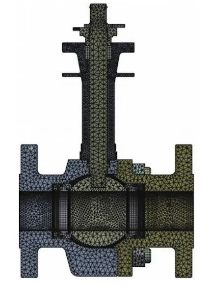
Figure 2 Grid model
The materials used in the valve and their associated properties are listed in Table 1. The valve body is made from A182 F316 stainless steel, while the sealing assembly consists of multiple sealing elements, including materials such as A194 8M and A320 B8M-CL2. The O-ring is made of low-temperature fluororubber, the gasket SS304, and the packing flexible graphite and SS316. The studs are fabricated from A194 8M, while the hexagonal nuts are made of A320 B8M-CL2.
Under normal operating conditions, the fluid temperature is maintained at -67°C. Consequently, the valve body wall temperature in contact with the fluid is also maintained at -67°C, and the convection heat transfer coefficient is specified as 4103.5 W/m²·°C. For the outer surface exposed to air, the convection heat transfer coefficient is assumed to be 10 W/m²·°C, with the air temperature specified as 22°C. The valve’s longitudinal section is treated as perfectly insulated.
Table 1 Ball valve materials
|
Material |
σ (MPa) |
σ0 (MPa) |
E (GPa) |
Poisson's Ratio |
|
A182 F316 |
515 |
205 |
193 |
0.28 |
|
A194 8M |
520 |
205 |
194 |
0.25 |
|
A320 B8M-CL2 |
620 |
345 |
193 |
0.29 |
|
SS304 |
515 |
205 |
193 |
0.28 |
|
Low-temperature fluororubber |
/ |
/ |
/ |
0.42 |
Thermal stress is calculated from the temperature field results. The longitudinal section of the valve is modeled with frictionless support, and the internal pressure is set to 7.5 MPa. To reduce the impact of the fixed support on the valve body in the stress calculation, a support body is added to the model. The support is a 50 mm-long cylinder with a radius equal to that of the flange. The right end of the support is fixed to the left flange face of the valve, and a fixed support is placed at the left end. The valve body and valve bonnet are secured with bolts. The total preload force is 4214.4 N, with 3000 N applied to the flange.
According to ASME Volume VIII, Part II, the safety factor for yield strength must be ≥1.5, and the safety factor for the strength limit must be ≥2.4. The allowable stress is calculated as the lower of the two values:
The allowable stress (Sm) for each material is presented in Table 2.
Table 2: Material Allowable Stress
|
Material |
σ (MPa) |
σ₀ (MPa) |
E (GPa) |
|
A182 F316 |
515 |
205 |
136.7 |
|
A194 8M |
520 |
205 |
136.7 |
|
A320 B8M-CL2 |
620 |
345 |
230 |
|
SS304 |
515 |
205 |
136.7 |
Figure 3 shows the simulation results for the temperature distribution in a cryogenic ball valve under normal operating conditions. The valve's lowest temperature is -67°C, occurring at the contact surface between the valve body and the fluid. The temperature increases along the valve stem, reaching a maximum of 12.8°C at the top. A notable temperature gradient exists between the valve stem and the extended bracket.
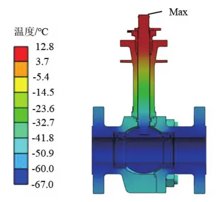
Figure 3: Valve body temperature distribution
Figure 4 illustrates the temperature distribution at the valve packing, which directly impacts the valve's sealing performance. The minimum temperature at the packing must stay above 0°C, as temperatures below this threshold could cause freezing, leading to seal failure. The temperature variation at the packing is minimal, with the lowest temperature at 5°C and the highest at 7°C, both exceeding 0°C. This confirms that the packing ensures effective sealing under normal operating conditions.
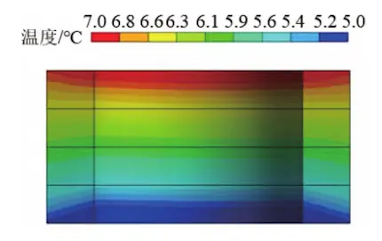
Figure 4: Packing Temperature Distribution
Figure 5 illustrates the stress distribution in the ball valve under thermal loading. As shown in the figure, the maximum thermal stress in the valve is 44.4 MPa, while the minimum is 0.006 MPa. The overall thermal stress in the valve body is significant due to the uneven temperature distribution and the fixed support on the left flange surface, which restricts deformation and increases the overall thermal stress. Although there is a significant temperature gradient between the valve stem and the extended bracket, both components are constrained only at the bottom end, with the upper ends free. As thermal deformation is unconstrained, the thermal stress in these components remains relatively low. Stress increases at the junctions between the valve stem and the valve ball, and between the extended bracket and the valve body, reaching approximately 10 MPa. The valve ball shows a uniform temperature distribution, resulting in low stress, with most areas remaining below 2 MPa.
Figure 6 shows the deformation distribution in the ball valve under thermal loading. As shown, due to the fixed constraint on the left flange surface, deformation gradually increases from left to right, with a maximum of 0.37 mm at the right flange surface.
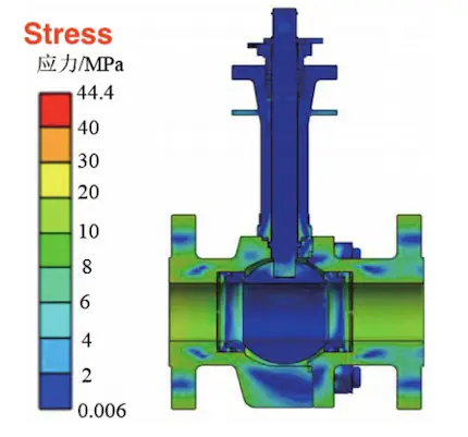
Figure 5 Stress Distribution of Valve Under Thermal Load
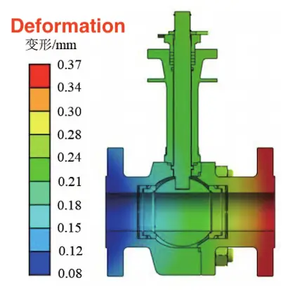
Figure 6 Deformation Distribution of Valve Under Thermal Load
Figure 7 shows the stress distribution in the ball valve under both thermal and force loading. As illustrated in the figure, the maximum thermal stress in the valve is 110 MPa, while the minimum is 0.006 MPa, both of which are below the allowable stress for each component’s material. The stress on the inner wall of the valve body spans approximately 40 to 55 MPa, while the stress on the inner wall of the valve ball is slightly lower, around 32 MPa, which is lower than the valve body stress. This is due to the uniform temperature distribution in the valve ball, resulting in minimal thermal stress. The stress in the valve stem and extended bracket remains very low, primarily because the upper ends of both components are free, allowing unconstrained deformation, which results in minimal thermal stress. Additionally, the internal pressure of the valve mainly affects the valve body and valve ball, resulting in very low stress on the valve stem and extended bracket. Compared to thermal loading alone, the stress on the sealing pair increases to approximately 40 MPa. The maximum stress occurs at the threaded hole of the left flange.
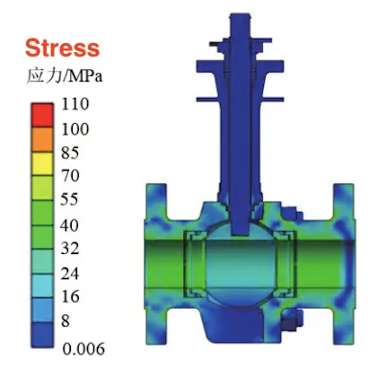
Figure 7: Valve stress distribution under thermal and force loads
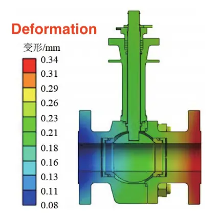
Figure 8: Valve deformation distribution under thermal and force loads
Figure 8 shows the deformation distribution in the ball valve under both thermal and force loading. As shown, the minimum deformation of the valve is 0.08 mm, while the maximum deformation is 0.34 mm. Compared to thermal loading alone, the maximum deformation is reduced. This is primarily due to the low temperature causing the valve to shrink, while the internal pressure induces a tendency for expansion. These two effects offset each other, ultimately reducing the maximum deformation of the valve. The deformation distribution remains consistent, gradually increasing from the left flange surface to the right flange surface.
This study employs finite element numerical simulation to analyze the cryogenic ball valve for solid-liquid two-phase flow in the low-temperature paraxylene preparation process system, determining the temperature, stress, and deformation distributions of the valve. The key conclusions are as follows:
- The valve structure is well-designed, with the minimum temperature at the packing being 5°C, which exceeds the required 0°C, ensuring effective sealing. A significant temperature gradient exists from the bottom to the top of the valve stem and extended bracket.
- The maximum stress in the valve under pure thermal load is 44 MPa, increasing to 110 MPa when a force load is applied. This suggests that under working conditions, the valve’s stress primarily results from the combined effects of internal pressure and preload, with thermal stress at low temperatures playing a secondary role.
- The deformation of the valve under both pure thermal load and combined thermal and force loading is similar, indicating that deformation is primarily due to thermal effects. The internal pressure of the valve interacts with the preload force, minimizing deformation caused by factors other than thermal expansion.
Previous: Application of Ceramic Valves in Calcium Carbide Slurry Production
Next: Research on Cavitation Suppression in V-Type Control Ball Valves

