Selection of Butterfly Valves for LNG Receiving Stations
Oct 17, 2024
On this page
LNG is classified as a Class A hazardous substance. The safety, stability, and continuity of LNG pipeline operations are critical. Cryogenic butterfly valves are commonly used in the main pipelines of LNG receiving stations. These valves are designed for online repair with three eccentric metal seated connected by butt welding. Currently, online repairable top-mounted cryogenic butterfly valves on the market are divided into two structures: top-mounted and side-mounted. The convenience and timeliness of on-site maintenance and repair are key factors in determining the shutdown duration of each device overhaul, playing a vital role in the efficient operation of the entire system. Additionally, to ensure the safety of the LNG receiving station throughout its lifecycle, the safety during on-site maintenance and the sealing performance of the valve after repair are crucial.
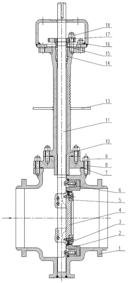
The structure of the side-mounted cryogenic butterfly valve is illustrated in Figure 1. The butt-welded connections at both ends of the valve body match the pipeline diameter. A maintenance hole is located on one side of the valve body. The movable valve seat is secured by a pressure ring, while the sealing ring is fixed by a pressure plate. The valve seat and pressure ring can be removed and repaired through the maintenance hole. A removable bottom cover is located at the base of the valve body, and an anti-flyout structure is present around the valve stem. The extended valve bonnet design accommodates the gasification space, ensuring that the working temperature of the valve stem packing meets operational requirements.
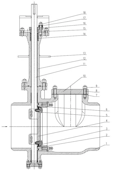
1. Valve bodies 2. Valve seats 3. Sealing rings 4. Butterfly plates 5. Pressure plates 6. Pressure rings 7. Gaskets 8. Studs 9. Nuts 10. Maintenance covers 11. Valve stems 12. Extended valve bonnets 13. Drip trays 14. Packing 15. Packing sleeves 16. Packing pressure plates 17. Studs 18. Nuts
Figure 1 Side-mounted Cryogenic Butterfly Valve Structure
The top-mounted low-temperature butterfly valve mechanism is illustrated in Figure 2. The butt-welded connections at both ends of the valve body match the pipeline diameter. The extended valve bonnet, valve seat, and integral valve body structure are secured by the pressure plate along with the sealing ring. The extended valve bonnet design accommodates the gasification space, and the lower end of the extended valve bonnet features an anti-flyout design. The bottom of the valve body is welded shut, and the sealing ring is replaced using the overall core-pulling method.
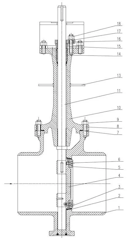
1. Valve bodies 2. Valve seats 3. Sealing rings 4. Butterfly plates 5. Pressure plates 6. Pressure rings 7. Gaskets 8. Studs 9. Nuts 10. Extended valve bonnets 11. Valve stems 13. Drip trays 14. Packing 15. Packing sleeves 16. Packing pressure plates 17. Studs 18. Nuts
Figure 2 Structure of Top-Mounted Low-Temperature Butterfly Valves
The pipeline at the LNG receiving station is affected by both ambient temperature and the low-temperature medium. To ensure the safety of pipeline operation, a butt-welded connection is used. After the pipeline and valve are welded, the primary task during pipeline purging is to remove welding slag, dust, and other debris. With the side-mounted butterfly valve, debris can be removed by opening the inspection compartment cover, making it easy to operate without affecting the overall structure or sealing of the valve. For the top-mounted butterfly valve, the gearbox must be removed, the butterfly plate rotated 180°, the middle flange bolts loosened, and then the extended valve bonnet, butterfly plate, and valve stem must be pulled out together to clear the debris in the valve cavity. This operation is cumbersome and demands a high level of technical expertise for reinstallation.
To ensure the safe operation of the pipeline, the entire system must undergo a strength test. Due to the large diameter of the main pipeline, gas cannot be used as the test medium. Only a water pressure test can be used, followed by nitrogen purging after the test. For the side-mounted butterfly valve, open the bottom cover to drain the water, allowing nitrogen to fully remove moisture and prevent ice formation during pre-cooling, which could cause the valve to fail to operate. The top-mounted butterfly valve uses a core-pulling design. For example, most top-mounted butterfly valves on the market have an integral or directly welded bottom bonnets to reduce leakage. A removable bottom cover is recommended for easier on-site purging and drying.
The inspection chamber of the side-mounted butterfly valve is easier to inspect online, and micro-leakage is easier to control. Compared to the top-mounted butterfly valve, the side-mounted valve has an additional external leakage point where the extended valve bonnet connects to the valve body. It is recommended to use anti-loosening bolts or a double-sealing structure to ensure micro-leakage control during long-term use.
To inspect the top-mounted butterfly valve, the upper valve bonnet must be opened, and the valve stem and butterfly plate disassembled together. After the inspection, the valve stem and butterfly plate are reinstalled. Structural alignment is challenging, and ensuring the reliability of the external sealing performance is difficult.
To inspect the top-mounted butterfly valve, the upper valve bonnet must be opened, and the valve stem and butterfly plate disassembled together. After the inspection, the valve stem and butterfly plate are reinstalled. Structural alignment is challenging, and ensuring the reliability of the external sealing performance is difficult.
Open the inspection chamber cover of the side-mounted butterfly valve. Loosen the pressure plate bolts. Remove the pressure plate and sealing ring, and either check and repair the sealing ring or replace it directly. For small diameters such as DN150 and DN200, a shortened special wrench is required to loosen the pressure plate bolts during maintenance. For large diameters such as DN600 and above, an extended special wrench is required to loosen the pressure plate bolts during maintenance. Maintenance personnel are not permitted to enter the pipeline for maintenance to ensure safety.
For the top-mounted butterfly valve, the gearbox must be disassembled first. Then, the valve stem is rotated 180° counterclockwise, and the valve stem and butterfly plate are removed from the valve cavity together, with the butterfly plate seal ring and related parts replaced outside. For large diameters such as DN500 and above, special tools are required to rotate the butterfly plate due to its heavy weight, and a crane of the appropriate tonnage is also required for lifting.
For the top-mounted butterfly valve, the gearbox must be disassembled first. Then, the valve stem is rotated 180° counterclockwise, and the valve stem and butterfly plate are removed from the valve cavity together, with the butterfly plate seal ring and related parts replaced outside. For large diameters such as DN500 and above, special tools are required to rotate the butterfly plate due to its heavy weight, and a crane of the appropriate tonnage is also required for lifting.
During the early stages of start-up or production operation, welding slag and other factors may cause damage to the sealing surfaces. The side-mounted butterfly valve can be disassembled through the inspection hole for online maintenance. If the valve seat of the top-mounted butterfly valve is damaged, the upper valve cover must be opened to disassemble the valve stem and butterfly plate together. The valve seat is fixed and cannot be replaced. Maintenance personnel cannot enter the pipeline and must use special grinding tools for repair. The maintenance period is long, keeping the LNG pipeline offline for an extended time. If the valve seat is severely scratched, the entire valve must be replaced by cutting it, which incurs high costs and poses safety risks.
After online repair, a sealing test cannot be performed, and the pipeline must be pre-cooled for an extended period before opening, making the sealing performance after repair crucial. The valve seat and sealing ring of the triple-eccentric butterfly valve have elliptical conical surfaces. Precise angle matching is required for them to seal properly; otherwise, excessive contact between the sealing ring and valve seat may occur, leading to sealing failure or damage to both components. After the side-mounted installation replaces the sealing ring, it is possible to directly observe whether the sealing ring and valve seat are fully aligned through the inspection chamber. If there is a deviation in alignment, the angle can be directly adjusted to meet the sealing requirements of the valve after repair. The sealing ring of the top-mounted butterfly valve must be replaced outside the valve body and then reinstalled in reverse following the disassembly steps. The butterfly plate and valve stem must be hoisted into the valve cavity and then rotated 180° to achieve a seal between the butterfly plate sealing ring and the valve seat. Since the two ends of the valve body are welded to the pipeline, it is impossible to observe or adjust through the flow channel hole, and the sealing condition of the valve after maintenance cannot be fully controlled. Leakage is likely to exceed BS6364 and other relevant standards.
The sealing ring and valve seat of the side-mounted butterfly valve can be removed from the maintenance chamber. For large-diameter valve seats, a hand winch can be used for on-site replacement or maintenance. The top-mounted butterfly valve requires an overall core-pulling method. For large-sized butterfly valves weighing several tons and located in restricted areas, such as those on top of storage tanks, large cranes and other heavy equipment are often required. The LNG receiving station has densely packed pipelines, and in some areas, large cranes and other equipment cannot access the site for lifting operations. Even if sufficient space is available for lifting, according to LNG station safety management regulations, multiple LNG pipelines near the crane must be isolated, and extensive safety isolation procedures must be implemented. The overall cost is high, and there is a significant operational safety risk. Some butterfly valves are installed on the lower level of the pipe gallery. Maintenance requires the complete disassembly of the valve stem and butterfly plate, and a large space is needed above the valve.
The movable valve seat of the side-mounted butterfly valve has a relatively complex structure, resulting in a long manufacturing period and high costs. The overall structure of the top-mounted butterfly valve is shorter than that of the side-mounted butterfly valve, and its shell is lighter, placing a lower load on the pipeline. Additionally, due to its light weight and the absence of a movable valve seat structure, the overall manufacturing cost is lower than that of the side-mounted butterfly valve.
According to the above comparison, the main disadvantage of the top-mounted butterfly valve is that the valve seat cannot be replaced. To address this problem, a top-mounted butterfly valve has been developed that can be repaired online at ultra-low temperatures. As shown in Figure 3, the butt-welded connections at both ends of the valve body match the pipeline diameter. The integral extended valve cover includes a movable valve seat, installed from the top and secured by a pressure ring. The sealing ring is fixed by a pressure plate. The extended valve bonnet design meets the requirements of the gasification space, and its lower end features an anti-flyout design. The bottom of the valve body is welded shut, and the sealing ring is replaced using the overall core-pulling method. Replacing the valve seat also requires overall core-pulling and reinstallation.
While this structure solves the issue of a movable valve seat, it increases the size of the valve body, and the complexity of the movable valve seat design diminishes the cost advantage. Compared to the side-mounted butterfly valve, replacing the valve seat requires overall core extraction, loosening the pressure ring bolts, and removing the four-part ring and valve seat. The steps are complicated, and the sealing performance cannot be tested online after reinstallation.
1. Valve bodies 2. Valve seats 3. Sealing rings 4. Butterfly plates 5. Pressure plates 6. Pressure rings 7. Gaskets 8. Studs 9. Nuts 10. Extended valve covers 11. Valve stems 13. Drip trays 14. Packing 15. Packing sleeves 16. Packing pressure plates 17. Studs 18. Nuts
Figure 3 Structure of movable valve seats for top-mounted low-temperature butterfly valves
While this structure solves the issue of a movable valve seat, it increases the size of the valve body, and the complexity of the movable valve seat design diminishes the cost advantage. Compared to the side-mounted butterfly valve, replacing the valve seat requires overall core extraction, loosening the pressure ring bolts, and removing the four-part ring and valve seat. The steps are complicated, and the sealing performance cannot be tested online after reinstallation.

1. Valve bodies 2. Valve seats 3. Sealing rings 4. Butterfly plates 5. Pressure plates 6. Pressure rings 7. Gaskets 8. Studs 9. Nuts 10. Extended valve covers 11. Valve stems 13. Drip trays 14. Packing 15. Packing sleeves 16. Packing pressure plates 17. Studs 18. Nuts
Figure 3 Structure of movable valve seats for top-mounted low-temperature butterfly valves
Previous: Problems and Solutions in Nuclear Power Valves
Next: Influence of Anti-Seismic Tooling on the Natural Frequency of Nuclear Power Valves

