Selecting Control Valves for Offshore Oil and Gas Fields
Jul 23, 2024
On this page
In the engineering design of offshore oil and gas field development projects, control valves are commonly used control devices in process control systems. These valves typically adjust the valve opening by receiving instructions from the central control system and are mainly used for regulating temperature, pressure, and liquid level. The main components of a control valve include the valve body, internal parts, actuator, and control accessories. Correctly selecting these four components is crucial to the overall functionality of the control valve.


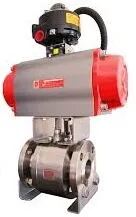
There are three types of control valves commonly used in offshore oil and gas field development projects: straight-through, angle, and ball control valves. Common straight-through valves include single-seat and sleeve types. The single-seat straight-through valve is suitable for conditions requiring low leakage, small flow, and a small pressure difference before and after the valve in the process flow. The structural design of the sleeve valve is generally balanced, with minimal unbalanced force at both ends of the valve core, and requires small actuator thrust. Therefore, it is recommended to use a sleeve valve when the pressure difference before and after the valve is large or the valve size is significant. However, the sleeve valve is not suitable for conditions containing dirty media such as solid particles or suspended matter.
Angle control valves are quite different. For media with high viscosity, suspended matter, or conditions prone to flashing, we usually choose angle valves. Reasonable selection of valve trim can make angle control valves suitable for conditions with high static pressure and large pressure differences. The advantages of ball control valves include strong sealing and flow capacity, low resistance to medium passage, and a wide adjustable range. The type of valve seat sealing material limits the selection of ball valves. The elastic valve seat has a relatively high sealing grade, but the actual working temperature greatly impacts the elastic material. In contrast, the metal valve seat is less affected by temperature, but it has relatively high leakage and is more difficult to process. The valve seat sealing material should be reasonably selected according to the application.
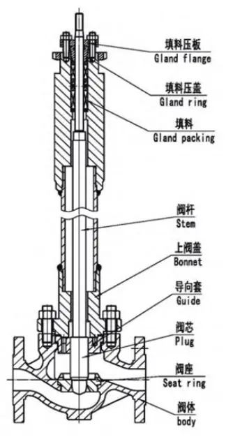
The connection method for the valve body end of the control valve in offshore oil and gas field development projects is usually a flange connection. The flange size matches the valve body size, and the flange pressure rating matches the flange surface form and pipeline information. The valve body of the control valve is generally selected as an integral casting, with commonly used materials including carbon steel, stainless steel, duplex stainless steel, Monel, and nickel aluminum bronze. The valve cover of the control valve is usually made from the same material as the valve body. The joint surface of the upper valve cover is typically reserved for the recess required for guiding and leveling the gasket and is connected with stud bolts. For high-pressure control valves, through bolts are generally used for connection. The upper valve cover types include standard, bellows, simple, with open heat plate (suitable for high-temperature conditions), and with extended sleeve (suitable for low-temperature conditions). The top of the upper valve cover is equipped with packing or a valve stem sealing gasket. When the medium temperature is greater than or equal to 200℃, the packing part is closer to the connection surface of the upper valve cover flange. Under high-temperature conditions, the medium is usually cast with cooling fins on the extended part of the upper valve cover for heat dissipation. When the medium temperature is less than or equal to -20℃, the flange and the packing are separated by a cylindrical long neck. The packing is installed on the long-necked upper valve cover, away from the cold area of the valve, to prevent the packing from freezing.
Bellows valve stem seals are usually selected for working conditions where valve stem leakage is not allowed. Additionally, bellows valve stem seals are often chosen for process media that are flammable, explosive, toxic, very expensive, or easily damaged. They are also suitable for vacuum applications. When the process medium passes over the surface of the reciprocating or rotating valve stem, it is prone to leaking. The packing can prevent this leakage through elastic methods. When the packing in contact with the valve stem surface is squeezed by the valve stem, it produces corresponding compression and deformation. Therefore, packing with high elasticity, easy deformation, and low friction should be selected. Furthermore, materials that are chemically inert and resistant to high temperatures and high pressure are more ideal for packing.
Polytetrafluoroethylene (PTFE) is a widely used valve packing. It is not only highly lubricating but also extremely chemically inert. It can be pressed as a whole or made into a V-ring. The disadvantage of integrally pressed PTFE packing is that its thermal expansion coefficient is high near room temperature, and it requires a high surface finish. Once the valve is installed with an actuator, the integral PTFE ring cannot be replaced. Another widely used packing is the graphite gasket. When the temperature is greater than 200°C, graphite is usually used for soft sealing packing. It is similar to pyrolytic graphite and has anisotropy and flexibility. It can be used in extremely high-temperature conditions (sublimation point is 6600℉), is extremely chemically inert, and has a low friction coefficient. Due to its high density, over-tightening the graphite packing may jam the valve stem.
The valve trim is an important part of the valve. The valve trim can not only adjust the area of the valve opening but also stipulate the relationship between the flow capacity of the medium through the valve opening and the valve core stroke. It can also cut off the medium. The realization of the function of the valve trim is inseparable from the valve body type, actuator, stem packing, and the properties of the medium acting on the valve trim. The selection of the valve needs to consider all parameters in association to obtain the best valve performance. In the selection process of the control valve, it is necessary to consider the type of valve trim: unbalanced, balanced, multi-stage, noise reduction, etc., and it is necessary to analyze the actual working conditions and calculation results before making specific selections. At the same time, pressure, temperature, medium viscosity, cavitation, flash evaporation, and the content of suspended matter in the medium will affect the design of the valve core. Single-seat valves have very good sealing performance. They usually use valve seats with narrow connection surfaces and high clamping force, or soft valve seats with strong elasticity. The selection of unbalanced and balanced internal parts can reduce the cost of selecting small differential pressure regulating actuators. Sleeve-type valve internal parts are also widely used in offshore oil and gas field development projects. They can reduce cavitation damage and valve noise and are very durable. Under the guidance of the sleeve, the valve plug combines with the pressure balance force passing through the valve core, and the valve core reduces the side tilt of the valve core, which can reduce the differential pressure load by more than or equal to 98%. Changing the type and size of the valve orifice can achieve excellent valve performance under high differential pressure.
The requirements for valve travel and actual working conditions for leakage levels are usually achieved through the actuator of the control valve. In some working conditions, if a pressure control valve is selected, it should be considered to amplify the actual possible pressure difference, meaning it is necessary to select an actuator that can provide a larger force. Otherwise, when the actual working conditions are abnormal, the actual pressure difference on site may be larger than the ideal value, and the valve may not open or close. Pneumatic diaphragm actuators are usually used in offshore oil and gas field development projects. There are two types of actuators: positive action and negative action. Neither type is directly related to the valve size specifications. After repeated verification and calculation, the diaphragm actuator can sufficiently overcome the unbalanced force generated by the valve body assembly when the valve is used. The main function of the actuator is to drive the valve action through the deviation verification signal. Regular valve manufacturers usually compile a catalog of the actuator range, which lists a wide range of actuator types and sizes. The advantages of diaphragm actuators are strong applicability and high cost performance. However, they require a large diaphragm area and a large diaphragm box when used. The larger the diaphragm box, the smaller the effective ability to maintain pressure. When used in conditions with large unbalanced forces, the entire assembly will appear top-heavy, and more stress problems may occur in the connection of the valve body assembly. Considering the impact of the marine environment, the housing material of the actuator in offshore oil and gas field development projects is generally carbon steel or alloy steel, plus anti-corrosion spraying. The instrument gas source of the offshore oil and gas field development project is usually 500 to 800 KpaG. The instrument gas usually experiences a certain pressure attenuation during the transmission process. Therefore, the actuator that can provide an output torque with a safety factor of 1.3 times at a driving pressure of 450 KpaG or less is generally selected.
Valve control accessories generally include valve positioners, valve position switches, solenoid valves, and handwheel mechanisms. Specific accessories need to be selected according to specific working conditions. Among them, the valve positioner can optimize the regulating performance of the control valve and achieve correct valve positioning. In offshore oil and gas field development projects, it is usually required that the dead zone parameter of the valve be less than or equal to 2%, the basic error of the control valve with the power distribution/gas valve positioner be less than ±10%, and the basic error of the control valve equipped with a digital valve positioner be less than ±1%.
Previous: Welding Seam Cracks in Main Steam Pipe Valves
Next: An Introduction to Control Valves


