Research on Low Noise of Butterfly Valves (Part One)
Feb 26, 2024
Abstract: numerical calculation and analysis on the flow field of butterfly valves are conducted and characteristics of the internal flow field and vortex structure of butterfly valves are obtained in this article. On this basis, a layered guide comb structure was proposed to optimize the design of the valve plate. The changes in the flow field and vortex characteristics in the valve before and after the optimized design were compared and experimentally verified. The test results show that the optimized design of the butterfly valve can achieve a significant reduction in vibration and noise levels without changing the hydraulic characteristics.
1. Introduction
A butterfly valve has become one of the fastest-growing valves in recent years due to its simple structure, good fluid control and sealing, small flow resistance, good flow capacity and great adjustable ratio. During the actual investigation, it was found that the butterfly valves currently in use have the problem of excessive vibration and noise. In order to reduce the vibration and noise of the ship piping system, the butterfly valve must be designed and optimized with low noise. The complex unsteady flow structure in the flow field inside the butterfly valve is the direct cause of the vibration noise. Therefore, analyzing the fine structure of the flow field inside the valve, especially the generation and evolution mechanism of vortex structures of different scales and their unsteady characteristics is a key to reducing vibration and noise in the butterfly valve. The general flow rules of the flow field in the butterfly valve are explored by conducting steady calculations on the flow field. On this basis, the valve plate’s geometric form is improved and designed. The flow field characteristics before and after optimization are compared and experimental tests are conducted to verify the reduction of the design. The vibration and noise reduction effect provides technical support for the optimal design of vibration and noise reduction of butterfly valves.
2. The prototype and improved design of the butterfly valve
2.1 The prototype and flow field characteristics of the butterfly valve
The research object is the DN80 center-type marine butterfly valve. The structure of this type of butterfly valve is relatively simple and mainly consists of two parts, that is, the butterfly valve body and the valve core. The butterfly valve body has a through-tube structure and is integrated with the upstream and downstream water inlet and outlet pipes. The valve core is an important component that forms the flow path of the valve. The change in the flow area caused by the change in the rotation angle of the valve core determines the hydraulic characteristics of the valve. It is also a part that needs to be studied and discussed in the design and optimization of the valve.
2.2 Flow field characteristics of prototype butterfly valves
A butterfly valve with a typical opening (valve core with a rotation angle of 45) was selected to establish and calculate the flow field model. Since the flow of fluid inside the valve body is relatively complex, the flow is very unstable and prone to vortex, backflow and other phenomena. In order to ensure the accuracy of the calculation, an inlet pipe with a length of 2 times the inlet diameter is added to the inlet of the butterfly valve, and the outlet pipe is increased to a length of 6 times the diameter of the outlet, allowing the flow in the inlet and outlet sections to fully develop and the flow to be stable. After calculation, it can be seen that the vortex structure in the butterfly valve shows strong three-dimensionality.
In order to observe the vortex structure in the valve more clearly, the Q law is used to display the vortex isosurface in the butterfly valve. The Q value is 0.1, and turbulent kinetic energy is used for coloring. The vortex structure behind the valve plate is radially symmetrical and presents a W-shape. In the high-speed jet area in the axial middle of the valve plate, the vortex intensity is small due to the small shearing effect between the fluids. The velocity difference of the moving fluid gradually increases, the shear effect gradually increases, and the vortex intensity gradually increases. The flow behind the valve plate is separated by the high-speed jet area in the middle to form two relatively independent upper and lower parts. The two parts of fluid form shedding vortices with a certain degree of symmetry. There is not just one vortex in this area, but a vortex structure composed of multiple vortices of different sizes, which occupies a large part of the lower part of the outlet chamber and spreads into the outlet pipe, which also affects the flow pattern in the outlet pipe.
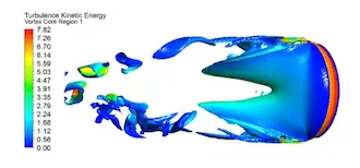
Figure 1 The schematic diagram of the vortex structure inside the prototype butterfly valve
2.3 The improved design plan of the butterfly valve
For the regulating butterfly valve, the flow rate is adjusted by changing the opening of the valve plate. The flow around the valve plate will produce a large-scale vortex structure behind the valve plate, which is the main source of pressure fluctuation and flow noise in the flow field. The layered guide comb structure is added to both sides of the valve plate to guide the flow around the fluid. At the same time, holes are drilled on the comb surface and a spoiler cylinder is set at the bottom of the flow channel between the combs. The small-scale vortices are rolled to further generate the flow. To achieve the effect of a uniform flow field, it plays the role of rectification and vortex elimination. The structure of the layered guide comb is shown in Figure 2.
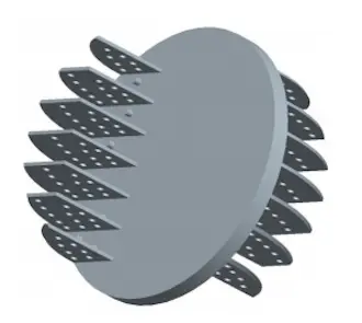
Figure 2 Layered guide combs
2.4 Flow field characteristics of the improved design scheme of the butterfly valve
The vortex structure in the flow field of the improved butterfly valve under the same opening (a valve core with a rotation angle of 45) was selected for analysis. The calculation boundary conditions are consistent with the calculation of the prototype butterfly valve. For the vortex structure, the Q law is also used to display the vortex isosurface in the butterfly valve, and turbulent kinetic energy is used for coloring. When the Q value is 0.1, there is no obvious vortex structure in the valve. Only when the Q value is 0.03 can an obvious vortex structure appear in the valve, as shown in Figure 3. It can be judged that the layered guide comb has a good rectifying effect and can significantly control the size and intensity of the large-scale vortex behind the valve disc, thereby reducing the intensity of the flow noise source in the valve.
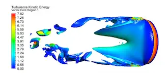
Figure 3 The schematic diagram of the vortex structure in the valve after improved design
2. The prototype and improved design of the butterfly valve
2.1 The prototype and flow field characteristics of the butterfly valve
The research object is the DN80 center-type marine butterfly valve. The structure of this type of butterfly valve is relatively simple and mainly consists of two parts, that is, the butterfly valve body and the valve core. The butterfly valve body has a through-tube structure and is integrated with the upstream and downstream water inlet and outlet pipes. The valve core is an important component that forms the flow path of the valve. The change in the flow area caused by the change in the rotation angle of the valve core determines the hydraulic characteristics of the valve. It is also a part that needs to be studied and discussed in the design and optimization of the valve.
2.2 Flow field characteristics of prototype butterfly valves
A butterfly valve with a typical opening (valve core with a rotation angle of 45) was selected to establish and calculate the flow field model. Since the flow of fluid inside the valve body is relatively complex, the flow is very unstable and prone to vortex, backflow and other phenomena. In order to ensure the accuracy of the calculation, an inlet pipe with a length of 2 times the inlet diameter is added to the inlet of the butterfly valve, and the outlet pipe is increased to a length of 6 times the diameter of the outlet, allowing the flow in the inlet and outlet sections to fully develop and the flow to be stable. After calculation, it can be seen that the vortex structure in the butterfly valve shows strong three-dimensionality.
In order to observe the vortex structure in the valve more clearly, the Q law is used to display the vortex isosurface in the butterfly valve. The Q value is 0.1, and turbulent kinetic energy is used for coloring. The vortex structure behind the valve plate is radially symmetrical and presents a W-shape. In the high-speed jet area in the axial middle of the valve plate, the vortex intensity is small due to the small shearing effect between the fluids. The velocity difference of the moving fluid gradually increases, the shear effect gradually increases, and the vortex intensity gradually increases. The flow behind the valve plate is separated by the high-speed jet area in the middle to form two relatively independent upper and lower parts. The two parts of fluid form shedding vortices with a certain degree of symmetry. There is not just one vortex in this area, but a vortex structure composed of multiple vortices of different sizes, which occupies a large part of the lower part of the outlet chamber and spreads into the outlet pipe, which also affects the flow pattern in the outlet pipe.

Figure 1 The schematic diagram of the vortex structure inside the prototype butterfly valve
2.3 The improved design plan of the butterfly valve
For the regulating butterfly valve, the flow rate is adjusted by changing the opening of the valve plate. The flow around the valve plate will produce a large-scale vortex structure behind the valve plate, which is the main source of pressure fluctuation and flow noise in the flow field. The layered guide comb structure is added to both sides of the valve plate to guide the flow around the fluid. At the same time, holes are drilled on the comb surface and a spoiler cylinder is set at the bottom of the flow channel between the combs. The small-scale vortices are rolled to further generate the flow. To achieve the effect of a uniform flow field, it plays the role of rectification and vortex elimination. The structure of the layered guide comb is shown in Figure 2.

Figure 2 Layered guide combs
2.4 Flow field characteristics of the improved design scheme of the butterfly valve
The vortex structure in the flow field of the improved butterfly valve under the same opening (a valve core with a rotation angle of 45) was selected for analysis. The calculation boundary conditions are consistent with the calculation of the prototype butterfly valve. For the vortex structure, the Q law is also used to display the vortex isosurface in the butterfly valve, and turbulent kinetic energy is used for coloring. When the Q value is 0.1, there is no obvious vortex structure in the valve. Only when the Q value is 0.03 can an obvious vortex structure appear in the valve, as shown in Figure 3. It can be judged that the layered guide comb has a good rectifying effect and can significantly control the size and intensity of the large-scale vortex behind the valve disc, thereby reducing the intensity of the flow noise source in the valve.

Figure 3 The schematic diagram of the vortex structure in the valve after improved design
Previous: Valves Used for the Intelligent Gas Field
Next: The Impact of Media on Valve Selection

