Problem Research of Special Valves
Feb 28, 2022
In recent years, China's valve industry has developed rapidly, but in the field of high-end special valves, there is still a big gap compared with foreign countries. With the strong support of national policies, manufacturing enterprises constantly innovate, digest and absorb foreign advanced technologies, and develop a large number of enterprises that master high-end valve materials, design, manufacturing and other core technologies, such as Newway, CNNC, Jiangsu Shentong, Dawson, etc. However, there is still a big gap compared with foreign countries in the fields of nuclear power, large-diameter welded ball valves of long-distance pipelines, high-temperature and high-pressure valves in the petrochemical industry and some special materials and non-standard high-end valves. This paper introduces the existing problems and technical difficulties of special valves at present. Summarizes and improves the materials, design and manufacture of corrosive medium valves, low-temperature ultra-low-temperature valves and high-temperature and high-pressure valves respectively.
Problems and Research of Special Valves
1. Corrosive medium valve
Some data show that the economic loss caused by valve replacement due to corrosion in the United States in a certain year is about 120 million US dollars, and the loss caused by boric acid corrosion is about 93 million US dollars. It can be seen that valve corrosion is very harmful to the service life and safety performance of valves. Valve corrosion mainly includes electrochemical corrosion, pitting corrosion, stress corrosion, hydrogen embrittlement, etc., among which electrochemical corrosion accounts for a large proportion. Many media are corrosive, even if the same media, under different temperatures, concentrations and pressures, has different corrosion rates and degrees on valves. Li Shulin mentioned that hydrogen sulfide corrosion, carbon dioxide corrosion and chloride ion corrosion are the three major types of corrosion faced by underwater oil production equipment. In addition, in order to meet the needs of wax removal and scale prevention, the complex corrosion caused by the addition of various chemical reagents and the superposition of various factors is the main reason for the failure of underwater valves. In view of the above corrosion types, many scholars have done a lot of research on valve corrosion prevention.
(1) Select suitable valve materials according to the service conditions such as acidity, concentration and corrosiveness of the medium. For example, carbon steel valves will not corrode basically under concentrated sulfuric acid, but when the concentration of sulfuric acid is below 50%, the corrosion rate of carbon steel will not be fast. Stainless steel has good corrosion resistance, but serious corrosion will occur in concentrated nitric acid with more than 96%.
(2) Improve and optimize the corrosive parts of the valve. Starting from the design, the parts of the valve that are easy to corrode are optimized, such as not using the threaded connection as much as possible, avoiding concave structure, setting drainage holes as much as possible, etc., so as to avoid corrosion caused by non-flow of the medium.
(3) Valve surface treatment technology. In view of the high cost and difficult processing of materials with good corrosion resistance, surface treatment technology is one of the most widely used methods at present, that is, attaching a layer of corrosion-resistant material to the inner surface of the valve to avoid direct contact between the valve metal and the medium, thus avoiding corrosion and improving the corrosion resistance of the valve. Fluorine material is an excellent corrosion-resistant material. At present, polytetrafluoroethylene (PTFE), polytetrafluoroethylene (FEP) and polytrichloroethylene (PCTFE) are the most widely used materials. The specific physical characteristics are shown in Table 1. From the atomic arrangement point of view, fluorine atoms surround the main chain structure of carbon atoms, and the carbon-fluorine bond is one of the strongest bonds, which makes the structure of fluorine materials stable. In addition, fluorine materials are nonmetallic materials, which have the advantages of self-lubrication, acid and alkali resistance and resistance to various organic solvents that metal materials do not have.
Table 1 Performance Comparison of PTFE, FEP and PCTFE
Density (g/cm3): PTFE 2.1-2.2, FEP 2.13-2.17, PCTFE 2.13
Shrinkage ratio (%): PTFE 1-5, FEP 2-5, PCTFE 1.5-2
Hardness: PTFE 58, FEP 25, PCTFE 20
Tensile strength (MPa): PTFE 14-45, FEP 20-22, PCTFE 32-40
Melting point (℃): PTFE 260, FEP 265, PCTFE 218
Expansion coefficient (10-5k-1): PTFE 10-12, FEP 8-10, PCTFE 4.5-7
Some scholars have improved the wear resistance, thermal stability and other properties of fluorine materials through modification technology to expand their application range. Sasikala et al. used Mg2SiO4 as filler to prepare Mg2SiO4-PTFE composites. Through experiments, it was found that Mg2SiO4 could effectively improve the hardness and thermal conductivity of materials and reduce the porosity of PTFE. Jiang Bo investigated the influence of glass fiber, halloysite, molybdenum disulfide and talcum powder on PTFE in different proportions. The results showed that the filler material could effectively improve the friction and wear, thermal expansion and mechanical properties of the material, and compared with the two-dimensional system, the elongation at break, tensile strength and bending strength of the three-dimensional system were increased by 40.0%, 2.3% and 7.1%, respectively, with obvious performance improvement. Yang Hao and others investigated the influence of Al2O3 filler with different content on the friction performance of PTFE. The results showed that with the increase of Al2O3 content, the friction coefficient increased and the wear amount decreased. The friction coefficient and wear volume of PTFE with different Al2O3 content were shown in Figure 1 and Figure 2, respectively.
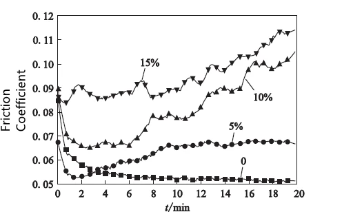
Fig. 1 Distribution of PTFE friction coefficient with different Al2O3 content
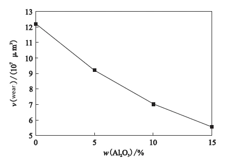
Fig. 2 Distribution of PTFE wear volume with different Al2O3 content
Spraying is also a widely used anti-corrosion technology in surface treatment technology, which is mainly used in working conditions where corrosion is not serious, such as atmosphere, brine, seawater and so on. Wang summarized the application of various nanostructured coatings in foreign naval vessels, among which nanostructured Al2O3/TiO2 coatings can significantly improve the service life of main plunger valves, valve stems, end shafts and other parts, and can save tens of billions of dollars in maintenance costs every year. The performance comparison between Al2O3/TiO2 nano-coating and ordinary coating is shown in Table 2.

Table 2 Comparison of properties between Al2O3/TiO2 nano-coating and ordinary coating
2. Low temperature and ultra-low temperature valve
Ultra-low temperature valves are mainly used to transport liquid cryogenic media, such as ethylene, liquefied natural gas (LNG), liquid oxygen, liquid nitrogen, liquid hydrogen and liquefied petroleum products. These media are low in temperature (below 150℃), flammable and explosive, and the gas-liquid expansion ratio is about 600: 1. Therefore, the design of ultra-low temperature valves is obviously different from that of conventional valves. Ultra-low temperature valves require very high materials, and unqualified materials will reduce the comprehensive performance of the shell and lead to leakage. Ultra-low temperature valves are required to have good sealing performance, and the valves should be cryogenically treated to make the metallographic structure of materials stable enough to avoid brittle fracture deformation caused by low temperature.
(1) low-temperature valve material
The material of cryogenic ultra-low temperature valve needs to have good low-temperature resistance, compatibility with medium, low thermal conductivity, good welding performance, etc. Austenitic stainless steel is the most widely used cryogenic valve material at present because of its excellent low-temperature toughness. Some scholars have compared the valve materials and found that 316 stainless steel is more suitable for low-temperature valve materials than 304 stainless steel. The reason is that 316 stainless steel contains molybdenum, which can effectively control the phase transformation. Because 304 stainless steel does not contain molybdenum, significant martensitic phase transformation will lead to large local stress and deformation of the valve, so it is necessary to carry out corresponding cryogenic treatment, and the relative cost is higher, so it is more reasonable to choose 316 stainless steel. Sunqi made AISI304, Ni40 and Ni60 cemented carbides by surface surfacing technology. Through the analysis of impact energy, fracture and intergranular structure, it was proved that the materials had a good low-temperature performance.
(2) Cryogenic treatment
Austenite will undergo a martensitic transformation in an ultra-low temperature environment, which will lead to volume expansion, shape and size changes, which is not conducive to valve strength and sealing performance. Even 316 stainless steel without martensitic transformation will be deformed due to thermal stress caused by uneven cold shrinkage. In the actual machining process, austenitic stainless steel will be subjected to cryogenic treatment twice to ensure the full transformation of martensite and minimize the deformation of the valve under low temperature and ultra-low temperature conditions. Zhou Weiwei used computer software to simulate cryogenic treatment, combined with the experiment, corrected the heat transfer coefficient, pointed out the key points of cryogenic treatment of austenitic stainless steel, and summarized the change law of austenitic stainless steel performance through different cryogenic treatment times and times. Liu Xiao and others studied the cryogenic treatment of 25 alloy steel and found that with the extension of cryogenic time and cryogenic times, all austenite structures were transformed into martensite structures, and the hardness and strength increased to 52.6HRC and 1 345 MPa, respectively. The strain and linear expansion coefficient decreased, and the low-temperature performance was stable. The hardness, elongation and yield strength distribution of samples under different cryogenic treatments are shown in Figures 3 and 4.
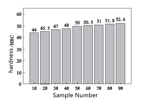
Fig. 3 Hardness distribution of samples under different cryogenic treatments
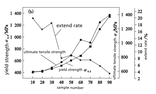
Fig. 4 Distribution of elongation and yield strength of samples under different cryogenic treatments
3. High temperature and high-pressure valve
With the rapid development of thermal power, the petrochemical industry, nuclear power, aerospace and other fields, the application of high-temperature and high-pressure valves has become more and more extensive, but there are also many problems.
(1) Long-term operation under high temperature, high pressure and alternating working conditions lead to valve creep, thermal fatigue and plastic deformation, which leads to the failure of valve moving parts and sealing structure.
(2) Transient thermal stress may exceed the maximum limit of steady-state design, resulting in insufficient valve strength.
(3) Under the working conditions of high-temperature difference and high-pressure difference, the liquid medium will gasify and generate bubbles. When the bubbles burst, it will generate an air hammer, which will generate huge pressure and cavitation, accompanied by strong vibration and noise, which will cause the valve performance to decline and the service life to be shortened. In view of the above problems, domestic and foreign workers have done a lot of research and improvement.
3.1 Improvement of materials and structures
Starting with the valve material and structure design, improve and perfect the moving parts and sealing structure of the valve. Some scholars have made finite element analyses of valves at high temperatures and found that the deformation of components with high temperatures is larger, while the deformation of components with low temperatures can be neglected. WU et al. found in the thermal stress analysis that the valve core and valve seat will be deformed greatly under high-temperature conditions, resulting in insufficient fit clearance, which will increase the friction between them and lead to the valve not working normally. Therefore, in the environment of the high-temperature medium, the valve is prone to thermal expansion, which leads to uneven changes in the sizes of various components, which reduces the fit clearance between various components of the valve, and leads to wear, bolt looseness, jamming, leakage and other phenomena of moving components. At the beginning of the design, the thermal expansion of materials at high temperatures should be fully considered.
First, materials with small expansion coefficient should be selected, and materials with similar expansion coefficients should be selected for all components of the whole valve as far as possible, so as to ensure that the deformation of each component tends to be the same under high-temperature conditions and avoid excessive deformation of individual components. Secondly, attention should be paid to other mechanical properties of valve materials such as high-temperature creep, hardness, impact resistance, etc., in order to cope with the long-term wear and medium impact of the valve under high-temperature working conditions and improve the reliability and safety of the valve. Some scholars have summarized the materials that can be used for high-temperature valves at different temperatures, as shown in Table 3.
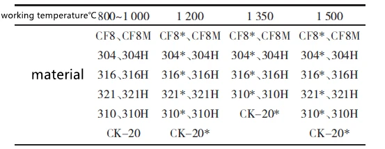
Note: When the operating temperature exceeds 1 000℃, it is only used when the carbon content is ≥0.04%.
Table 3 Materials available for high-temperature valves at different temperatures
For the sealing structure, graphite material can be used instead of traditional rubber sealing materials, such as expanded graphite packing (Figure 5) and reinforced graphite packing, and the maximum service temperature can reach 600℃. Because of its soft texture, it can still play a good sealing effect even if deformed at high temperatures, and its chemical performance is stable. A graphite gasket with a metal inner reinforcing ring and outer positioning ring can be selected to improve locking force and sealing strength. The elastic seal can be selected, and the spring can be used to give corresponding compensation adjustments to ensure the safe operation of the valve. Stellite alloy and boron chromium alloy can be selected as the sealing surface of the valve, and the change rule of hardness with temperature is shown in Figure 6. At 500℃, the hardness of Cr14 and 9Cr10Mo materials drops sharply, while Stellite alloy and boron chromium alloy still maintain high hardness at 700℃, which can effectively avoid valve failure caused by plastic deformation of the sealing surface.
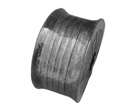
Fig. 5 Expanded graphite packing
3.2 Working condition simulation analysis
Based on the finite element analysis software, the coupling of fluid, temperature and structure is analyzed, and the actual working state of the reduction valve is analyzed. The finite element analysis method is mainly divided into single field analysis and coupled field analysis. The single field only considers the temperature field to analyze the valve. Cheng Weidao used ANSYS to analyze the temperature field of the right-angle globe valve under high temperature and high-pressure conditions, and obtained the temperature field distribution of the dangerous parts of the valve, and adjusted the material and wall thickness of the valve according to the thermal position and peak value to improve the safety of the valve. Different parts of the electric regulating valve are analyzed from three angles of Li Yujie steady temperature field, thermal stress field and thermal deformation field. The results show that the thermal stress at the packing is the largest, followed by the copper guide sleeve. The bolt head material with better mechanical properties should be selected, and it is proposed that the heat sink structure can effectively reduce the valve temperature. He Qingzhong and others used the Singhal cavitation model and mass transfer equation to analyze the influence of thermodynamics on the cavitation of the control valve. It was found that the depressurization process of the control valve would cause partial energy conversion and latent heat absorption of vaporization. With the increase of medium temperature, the temperature rise of the throttling cavitation area is larger, and the influence range of cavitation is enlarged, as shown in Figure 8.
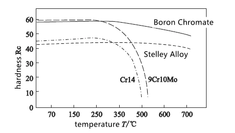
Fig. 6 Variation of the hardness of different materials with temperature
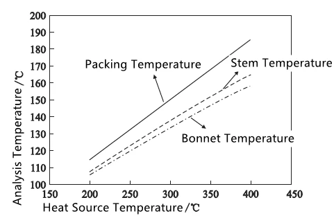
Fig. 7 Temperature change trend of each component at different temperatures
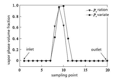
Fig. 8 Vaporization volume fraction under different pressure conditions
Although the temperature field can get the temperature distribution and the micro-deformation of the valve caused by thermal stress, it only analyzes the single factor, ignoring the influence of structure, fluid and other factors. At present, most of the temperature field analysis is a steady-state thermal analysis, that is, the temperature field distribution of the valve can only be obtained by maintaining a fixed temperature, but the temperature change with time can not be obtained, so it is impossible to quantitatively analyze the temperature field distribution in special states such as valve opening and closing and to obtain the influence of actual comprehensive stress on the structural strength of the valve. Coupling field involves thermal-solid two-field coupling analysis and thermal-fluid-solid three-field coupling analysis, that is, after the temperature field distribution is obtained, it is used as the boundary load to analyze the stress field. Liu Jinliang used Workbench to calculate the coupling stress of pressure field and temperature field, and determine the minimum wall thickness under the combined action of thermal stress and compressive stress. Lin Peng analyzed the temperature field and stress field of the bypass valve body of steam turbine under its standby and operating conditions, in which the comprehensive stress and temperature gradient of the valve body at the inlet of the valve under standby conditions were the largest. The distribution of comprehensive stress value with time under operating conditions is shown in Figure 9. The comprehensive stress of the valve body shows a process of first decreasing, then increasing and then decreasing until it is stable, with the maximum stress of 85.6 MPa. Li Shuxun used Fluent and ANSYS software to analyze the strength and fatigue of the valve under transient thermal shock by means of the thermal fluid-solid coupling method. The results show that transient thermal shock under pressure has a great influence on the temperature field, structural strength, fatigue life and sensitivity of the valve body. The variation of valve stress with time under thermal shock is shown in Figure 10.
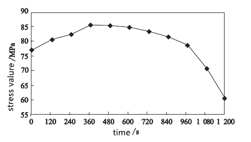
Fig. 9 Distribution of comprehensive stress values with time under operating conditions
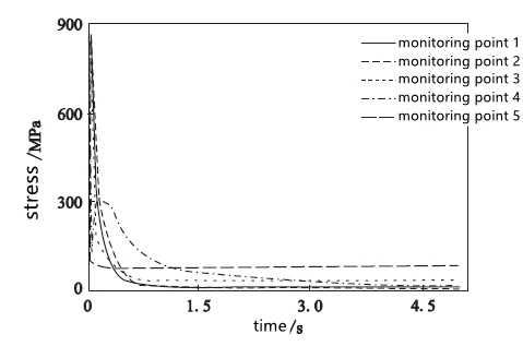
Fig. 10 Variation of valve stress with time under thermal shock
Compared with single-field analysis, coupled-field analysis can combine the actual situation, consider many problems such as fluid impact, thermal stress and structural strength, and analyze the service life and fatigue strength of valves more accurately. However, due to the complex superposition of composite fields, the problem of setting boundary conditions, and a large amount of calculation, it is easy to have no solution. However, it is still undeniable that the thermal-fluid-solid coupling has greatly promoted the design and application of high-temperature and high-pressure valves.
Conclusion
This paper introduces the existing problems and technical difficulties of special valves in China summarizes the research progress of high-end valves and puts forward the improvement direction for valve design and research.
(1) At present, more research still stays in the steady-state temperature field analysis, and transient temperature field analysis should be carried out, combined with a fluid, solid structure and other aspects, the thermal-fluid-solid coupling should be carried out, and all-round analysis and valve design should be carried out.
(2) On the basis of considering thermal stress, fluid and strength, the reference factors of fatigue and service life should be introduced, but there is little research on this aspect at present.
(3) Although fluid and temperature have a greater influence on structural strength, thermal-solid coupling and thermal-fluid-solid coupling still belong to the one-way coupling range, and the research on the bidirectional coupling field should be further strengthened.
Problems and Research of Special Valves
1. Corrosive medium valve
Some data show that the economic loss caused by valve replacement due to corrosion in the United States in a certain year is about 120 million US dollars, and the loss caused by boric acid corrosion is about 93 million US dollars. It can be seen that valve corrosion is very harmful to the service life and safety performance of valves. Valve corrosion mainly includes electrochemical corrosion, pitting corrosion, stress corrosion, hydrogen embrittlement, etc., among which electrochemical corrosion accounts for a large proportion. Many media are corrosive, even if the same media, under different temperatures, concentrations and pressures, has different corrosion rates and degrees on valves. Li Shulin mentioned that hydrogen sulfide corrosion, carbon dioxide corrosion and chloride ion corrosion are the three major types of corrosion faced by underwater oil production equipment. In addition, in order to meet the needs of wax removal and scale prevention, the complex corrosion caused by the addition of various chemical reagents and the superposition of various factors is the main reason for the failure of underwater valves. In view of the above corrosion types, many scholars have done a lot of research on valve corrosion prevention.
(1) Select suitable valve materials according to the service conditions such as acidity, concentration and corrosiveness of the medium. For example, carbon steel valves will not corrode basically under concentrated sulfuric acid, but when the concentration of sulfuric acid is below 50%, the corrosion rate of carbon steel will not be fast. Stainless steel has good corrosion resistance, but serious corrosion will occur in concentrated nitric acid with more than 96%.
(2) Improve and optimize the corrosive parts of the valve. Starting from the design, the parts of the valve that are easy to corrode are optimized, such as not using the threaded connection as much as possible, avoiding concave structure, setting drainage holes as much as possible, etc., so as to avoid corrosion caused by non-flow of the medium.
(3) Valve surface treatment technology. In view of the high cost and difficult processing of materials with good corrosion resistance, surface treatment technology is one of the most widely used methods at present, that is, attaching a layer of corrosion-resistant material to the inner surface of the valve to avoid direct contact between the valve metal and the medium, thus avoiding corrosion and improving the corrosion resistance of the valve. Fluorine material is an excellent corrosion-resistant material. At present, polytetrafluoroethylene (PTFE), polytetrafluoroethylene (FEP) and polytrichloroethylene (PCTFE) are the most widely used materials. The specific physical characteristics are shown in Table 1. From the atomic arrangement point of view, fluorine atoms surround the main chain structure of carbon atoms, and the carbon-fluorine bond is one of the strongest bonds, which makes the structure of fluorine materials stable. In addition, fluorine materials are nonmetallic materials, which have the advantages of self-lubrication, acid and alkali resistance and resistance to various organic solvents that metal materials do not have.
Table 1 Performance Comparison of PTFE, FEP and PCTFE
Density (g/cm3): PTFE 2.1-2.2, FEP 2.13-2.17, PCTFE 2.13
Shrinkage ratio (%): PTFE 1-5, FEP 2-5, PCTFE 1.5-2
Hardness: PTFE 58, FEP 25, PCTFE 20
Tensile strength (MPa): PTFE 14-45, FEP 20-22, PCTFE 32-40
Melting point (℃): PTFE 260, FEP 265, PCTFE 218
Expansion coefficient (10-5k-1): PTFE 10-12, FEP 8-10, PCTFE 4.5-7
Some scholars have improved the wear resistance, thermal stability and other properties of fluorine materials through modification technology to expand their application range. Sasikala et al. used Mg2SiO4 as filler to prepare Mg2SiO4-PTFE composites. Through experiments, it was found that Mg2SiO4 could effectively improve the hardness and thermal conductivity of materials and reduce the porosity of PTFE. Jiang Bo investigated the influence of glass fiber, halloysite, molybdenum disulfide and talcum powder on PTFE in different proportions. The results showed that the filler material could effectively improve the friction and wear, thermal expansion and mechanical properties of the material, and compared with the two-dimensional system, the elongation at break, tensile strength and bending strength of the three-dimensional system were increased by 40.0%, 2.3% and 7.1%, respectively, with obvious performance improvement. Yang Hao and others investigated the influence of Al2O3 filler with different content on the friction performance of PTFE. The results showed that with the increase of Al2O3 content, the friction coefficient increased and the wear amount decreased. The friction coefficient and wear volume of PTFE with different Al2O3 content were shown in Figure 1 and Figure 2, respectively.

Fig. 1 Distribution of PTFE friction coefficient with different Al2O3 content

Fig. 2 Distribution of PTFE wear volume with different Al2O3 content
Spraying is also a widely used anti-corrosion technology in surface treatment technology, which is mainly used in working conditions where corrosion is not serious, such as atmosphere, brine, seawater and so on. Wang summarized the application of various nanostructured coatings in foreign naval vessels, among which nanostructured Al2O3/TiO2 coatings can significantly improve the service life of main plunger valves, valve stems, end shafts and other parts, and can save tens of billions of dollars in maintenance costs every year. The performance comparison between Al2O3/TiO2 nano-coating and ordinary coating is shown in Table 2.

Table 2 Comparison of properties between Al2O3/TiO2 nano-coating and ordinary coating
2. Low temperature and ultra-low temperature valve
Ultra-low temperature valves are mainly used to transport liquid cryogenic media, such as ethylene, liquefied natural gas (LNG), liquid oxygen, liquid nitrogen, liquid hydrogen and liquefied petroleum products. These media are low in temperature (below 150℃), flammable and explosive, and the gas-liquid expansion ratio is about 600: 1. Therefore, the design of ultra-low temperature valves is obviously different from that of conventional valves. Ultra-low temperature valves require very high materials, and unqualified materials will reduce the comprehensive performance of the shell and lead to leakage. Ultra-low temperature valves are required to have good sealing performance, and the valves should be cryogenically treated to make the metallographic structure of materials stable enough to avoid brittle fracture deformation caused by low temperature.
(1) low-temperature valve material
The material of cryogenic ultra-low temperature valve needs to have good low-temperature resistance, compatibility with medium, low thermal conductivity, good welding performance, etc. Austenitic stainless steel is the most widely used cryogenic valve material at present because of its excellent low-temperature toughness. Some scholars have compared the valve materials and found that 316 stainless steel is more suitable for low-temperature valve materials than 304 stainless steel. The reason is that 316 stainless steel contains molybdenum, which can effectively control the phase transformation. Because 304 stainless steel does not contain molybdenum, significant martensitic phase transformation will lead to large local stress and deformation of the valve, so it is necessary to carry out corresponding cryogenic treatment, and the relative cost is higher, so it is more reasonable to choose 316 stainless steel. Sunqi made AISI304, Ni40 and Ni60 cemented carbides by surface surfacing technology. Through the analysis of impact energy, fracture and intergranular structure, it was proved that the materials had a good low-temperature performance.
(2) Cryogenic treatment
Austenite will undergo a martensitic transformation in an ultra-low temperature environment, which will lead to volume expansion, shape and size changes, which is not conducive to valve strength and sealing performance. Even 316 stainless steel without martensitic transformation will be deformed due to thermal stress caused by uneven cold shrinkage. In the actual machining process, austenitic stainless steel will be subjected to cryogenic treatment twice to ensure the full transformation of martensite and minimize the deformation of the valve under low temperature and ultra-low temperature conditions. Zhou Weiwei used computer software to simulate cryogenic treatment, combined with the experiment, corrected the heat transfer coefficient, pointed out the key points of cryogenic treatment of austenitic stainless steel, and summarized the change law of austenitic stainless steel performance through different cryogenic treatment times and times. Liu Xiao and others studied the cryogenic treatment of 25 alloy steel and found that with the extension of cryogenic time and cryogenic times, all austenite structures were transformed into martensite structures, and the hardness and strength increased to 52.6HRC and 1 345 MPa, respectively. The strain and linear expansion coefficient decreased, and the low-temperature performance was stable. The hardness, elongation and yield strength distribution of samples under different cryogenic treatments are shown in Figures 3 and 4.

Fig. 3 Hardness distribution of samples under different cryogenic treatments

Fig. 4 Distribution of elongation and yield strength of samples under different cryogenic treatments
3. High temperature and high-pressure valve
With the rapid development of thermal power, the petrochemical industry, nuclear power, aerospace and other fields, the application of high-temperature and high-pressure valves has become more and more extensive, but there are also many problems.
(1) Long-term operation under high temperature, high pressure and alternating working conditions lead to valve creep, thermal fatigue and plastic deformation, which leads to the failure of valve moving parts and sealing structure.
(2) Transient thermal stress may exceed the maximum limit of steady-state design, resulting in insufficient valve strength.
(3) Under the working conditions of high-temperature difference and high-pressure difference, the liquid medium will gasify and generate bubbles. When the bubbles burst, it will generate an air hammer, which will generate huge pressure and cavitation, accompanied by strong vibration and noise, which will cause the valve performance to decline and the service life to be shortened. In view of the above problems, domestic and foreign workers have done a lot of research and improvement.
3.1 Improvement of materials and structures
Starting with the valve material and structure design, improve and perfect the moving parts and sealing structure of the valve. Some scholars have made finite element analyses of valves at high temperatures and found that the deformation of components with high temperatures is larger, while the deformation of components with low temperatures can be neglected. WU et al. found in the thermal stress analysis that the valve core and valve seat will be deformed greatly under high-temperature conditions, resulting in insufficient fit clearance, which will increase the friction between them and lead to the valve not working normally. Therefore, in the environment of the high-temperature medium, the valve is prone to thermal expansion, which leads to uneven changes in the sizes of various components, which reduces the fit clearance between various components of the valve, and leads to wear, bolt looseness, jamming, leakage and other phenomena of moving components. At the beginning of the design, the thermal expansion of materials at high temperatures should be fully considered.
First, materials with small expansion coefficient should be selected, and materials with similar expansion coefficients should be selected for all components of the whole valve as far as possible, so as to ensure that the deformation of each component tends to be the same under high-temperature conditions and avoid excessive deformation of individual components. Secondly, attention should be paid to other mechanical properties of valve materials such as high-temperature creep, hardness, impact resistance, etc., in order to cope with the long-term wear and medium impact of the valve under high-temperature working conditions and improve the reliability and safety of the valve. Some scholars have summarized the materials that can be used for high-temperature valves at different temperatures, as shown in Table 3.

Note: When the operating temperature exceeds 1 000℃, it is only used when the carbon content is ≥0.04%.
Table 3 Materials available for high-temperature valves at different temperatures
For the sealing structure, graphite material can be used instead of traditional rubber sealing materials, such as expanded graphite packing (Figure 5) and reinforced graphite packing, and the maximum service temperature can reach 600℃. Because of its soft texture, it can still play a good sealing effect even if deformed at high temperatures, and its chemical performance is stable. A graphite gasket with a metal inner reinforcing ring and outer positioning ring can be selected to improve locking force and sealing strength. The elastic seal can be selected, and the spring can be used to give corresponding compensation adjustments to ensure the safe operation of the valve. Stellite alloy and boron chromium alloy can be selected as the sealing surface of the valve, and the change rule of hardness with temperature is shown in Figure 6. At 500℃, the hardness of Cr14 and 9Cr10Mo materials drops sharply, while Stellite alloy and boron chromium alloy still maintain high hardness at 700℃, which can effectively avoid valve failure caused by plastic deformation of the sealing surface.

Fig. 5 Expanded graphite packing
3.2 Working condition simulation analysis
Based on the finite element analysis software, the coupling of fluid, temperature and structure is analyzed, and the actual working state of the reduction valve is analyzed. The finite element analysis method is mainly divided into single field analysis and coupled field analysis. The single field only considers the temperature field to analyze the valve. Cheng Weidao used ANSYS to analyze the temperature field of the right-angle globe valve under high temperature and high-pressure conditions, and obtained the temperature field distribution of the dangerous parts of the valve, and adjusted the material and wall thickness of the valve according to the thermal position and peak value to improve the safety of the valve. Different parts of the electric regulating valve are analyzed from three angles of Li Yujie steady temperature field, thermal stress field and thermal deformation field. The results show that the thermal stress at the packing is the largest, followed by the copper guide sleeve. The bolt head material with better mechanical properties should be selected, and it is proposed that the heat sink structure can effectively reduce the valve temperature. He Qingzhong and others used the Singhal cavitation model and mass transfer equation to analyze the influence of thermodynamics on the cavitation of the control valve. It was found that the depressurization process of the control valve would cause partial energy conversion and latent heat absorption of vaporization. With the increase of medium temperature, the temperature rise of the throttling cavitation area is larger, and the influence range of cavitation is enlarged, as shown in Figure 8.

Fig. 6 Variation of the hardness of different materials with temperature

Fig. 7 Temperature change trend of each component at different temperatures

Fig. 8 Vaporization volume fraction under different pressure conditions
Although the temperature field can get the temperature distribution and the micro-deformation of the valve caused by thermal stress, it only analyzes the single factor, ignoring the influence of structure, fluid and other factors. At present, most of the temperature field analysis is a steady-state thermal analysis, that is, the temperature field distribution of the valve can only be obtained by maintaining a fixed temperature, but the temperature change with time can not be obtained, so it is impossible to quantitatively analyze the temperature field distribution in special states such as valve opening and closing and to obtain the influence of actual comprehensive stress on the structural strength of the valve. Coupling field involves thermal-solid two-field coupling analysis and thermal-fluid-solid three-field coupling analysis, that is, after the temperature field distribution is obtained, it is used as the boundary load to analyze the stress field. Liu Jinliang used Workbench to calculate the coupling stress of pressure field and temperature field, and determine the minimum wall thickness under the combined action of thermal stress and compressive stress. Lin Peng analyzed the temperature field and stress field of the bypass valve body of steam turbine under its standby and operating conditions, in which the comprehensive stress and temperature gradient of the valve body at the inlet of the valve under standby conditions were the largest. The distribution of comprehensive stress value with time under operating conditions is shown in Figure 9. The comprehensive stress of the valve body shows a process of first decreasing, then increasing and then decreasing until it is stable, with the maximum stress of 85.6 MPa. Li Shuxun used Fluent and ANSYS software to analyze the strength and fatigue of the valve under transient thermal shock by means of the thermal fluid-solid coupling method. The results show that transient thermal shock under pressure has a great influence on the temperature field, structural strength, fatigue life and sensitivity of the valve body. The variation of valve stress with time under thermal shock is shown in Figure 10.

Fig. 9 Distribution of comprehensive stress values with time under operating conditions

Fig. 10 Variation of valve stress with time under thermal shock
Compared with single-field analysis, coupled-field analysis can combine the actual situation, consider many problems such as fluid impact, thermal stress and structural strength, and analyze the service life and fatigue strength of valves more accurately. However, due to the complex superposition of composite fields, the problem of setting boundary conditions, and a large amount of calculation, it is easy to have no solution. However, it is still undeniable that the thermal-fluid-solid coupling has greatly promoted the design and application of high-temperature and high-pressure valves.
Conclusion
This paper introduces the existing problems and technical difficulties of special valves in China summarizes the research progress of high-end valves and puts forward the improvement direction for valve design and research.
(1) At present, more research still stays in the steady-state temperature field analysis, and transient temperature field analysis should be carried out, combined with a fluid, solid structure and other aspects, the thermal-fluid-solid coupling should be carried out, and all-round analysis and valve design should be carried out.
(2) On the basis of considering thermal stress, fluid and strength, the reference factors of fatigue and service life should be introduced, but there is little research on this aspect at present.
(3) Although fluid and temperature have a greater influence on structural strength, thermal-solid coupling and thermal-fluid-solid coupling still belong to the one-way coupling range, and the research on the bidirectional coupling field should be further strengthened.
Previous: Intelligentization of Electric Valves
Next: Forms, End Distance and Flow Path of Regulating Valves


