Pneumatic Valves Used in Cement Companies
Oct 16, 2023
Pneumatic valves have revolutionized the cement industry, providing efficient and reliable control over various processes. These valves play a crucial role in regulating the flow of materials, such as cement, water, and additives, throughout the production line.
One of the primary applications of pneumatic valves in cement companies is in the raw material handling process. These valves are used to control the flow of limestone, clay, and other materials into crushers and mills. By accurately adjusting the valve position, operators can ensure a consistent feed rate and optimize grinding efficiency.
Furthermore, pneumatic valves are essential in controlling the flow of air and fuel into kilns for clinker production. The precise regulation of these inputs is critical to maintaining optimal combustion conditions within the kiln. Pneumatic valves enable operators to adjust airflow rates and fuel ratios promptly, ensuring maximum energy efficiency while minimizing emissions.
Another vital application of pneumatic valves is in cement packaging lines. These valves regulate the flow of cement into bags or containers with high accuracy. By maintaining consistent filling rates, they help prevent wastage and ensure that customers receive precisely measured quantities.
In conclusion, pneumatic valves have become indispensable components in cement companies due to their ability to provide accurate control over various processes. Their use in raw material handling, kiln operations, and packaging lines has significantly improved productivity while reducing waste and environmental impact. As technology continues to advance, we can expect further enhancements in pneumatic valve design and functionality for even greater efficiency in cement production.
The number of valves used in cement enterprises is second only to electric motors, and they are responsible for important functions such as adjustment and conversion. Because there are many types of valves, and some non-electronic control professional designers lack understanding of the electronic control profession, various problems often occur during design, selection and ordering.
1.1 Types and control of pneumatic valves
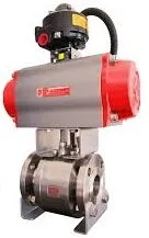
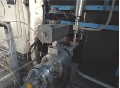
Most of the pneumatic valves commonly used in cement companies are on-off pneumatic globe valves, such as the quick safety globe valve at the coal mill inlet and outlet, the pneumatic feeding valve at the end of the kiln, and the pneumatic gate valve for the kiln elevator to dump the warehouse. In addition, a pneumatic flow regulating valve for homogenizing the bottom discharge of the warehouse is also used, which requires a pneumatic positioner. The characteristic of pneumatic valves is that they act quickly but have relatively small torque. Pneumatic valves are composed of pneumatic actuators and valves. The most commonly used solenoid valve is a type of pneumatic actuator. The valve is composed of a cylinder and a valve body. The switch type uses a solenoid valve to control the direction of compressed air to drive the cylinder to reciprocate, thereby controlling the opening and closing of the valve. The flow valve needs to control the pneumatic actuator with an electrical signal to adjust the flow. Generally, the valve opening needs to be set through the PID loop in the program.
The most commonly used solenoid valve in cement companies is a two-position three-way valve, and its electronic control methods are divided into two types: single solenoid control and double solenoid control. The single solenoid control has only one solenoid coil. The action principle is that energizing the coil causes the valve core to move, thereby changing the direction of the airflow. Once the coil is powered off, the valve core will automatically return to the initial position through the action of the return spring, and the airflow direction will be reversed. The dual solenoid control has two electromagnetic coils. The action principle is that when energizing the forward action coil, the valve core moves forward and maintains it until the reaction action coil is energized; when energizing the reaction coil, the valve core moves in the reverse direction and maintains it until the positive action coil is energized.
1.2 Common problems and solutions during debugging of pneumatic valves
(1) Position signal
It is necessary to check the position switch. If it is a magnetic switch installed on the cylinder body, you can judge whether it is normal by observing the indicator light or directly measuring it. If it is a limit switch installed on the valve body, it is the same as the limit switch of the electric valve mentioned above.
(2) The valve does not move after the drive is issued.
In this case, eliminate mechanical problems, such as whether the air source is normal or the valve is stuck. After confirming that there are no mechanical problems,
check whether the coil of the solenoid valve is energized normally or the voltage is normal. If the power supply is normal, the coil is burned. This situation is easy to occur during operation. It is generally caused by the operating voltage being too high, which causes the current in the coil to increase. Determining whether the coil is burned can be achieved by measuring the coil resistance. In the design, if some pneumatic valves do not need frequent operation, you can choose dual electric control. In this way, the coil does not need to be energized frequently, which can effectively extend its service life.
Previous: Electric Valves Used in Cement Companies
Next: Lifting Plug Valves


