Flow Field Characteristics and Erosion Mechanisms in Ball Valves with Various Seat Structures
Mar 31, 2025
Erosion in ball valves operating in solid particle-laden fluids impacts their reliability and service life. This study investigates the flow field characteristics and erosion mechanisms of metal double-seal floating ball valves. Experimental results show that at 10% and 20% relative openings, the average flow rate is higher than at other openings, indicating that small variations in seat structure have a significant impact on flow field characteristics. These findings provide valuable insights for optimizing ball valve seat design.
Metal double-seal ball valves play a critical role in industrial process control, where their flow field characteristics and erosion mechanisms directly influence performance. In harsh operating conditions, high-velocity fluid impact and solid particle abrasion accelerate valve erosion. Therefore, analyzing the erosion mechanism is crucial for improving valve reliability and extending service life. However, most existing studies focus on material properties, often overlooking a systematic analysis of the erosion mechanism. To address this gap, this study uses computational fluid dynamics (CFD) and the discrete phase model (DPM) to assess the flow distribution of different seat structures at varying openings and their effect on erosion.
A full-scale geometric model of the metal double-seal floating ball valve is constructed to address frequent internal leakage issues in the pipeline system connecting the regenerator, receiver, and lock hopper, as shown in Figure 1. The valve has a nominal flow channel diameter of 80 mm. To ensure fully developed flow upstream and downstream of the valve and enhance computational accuracy, the fluid domain's upstream and downstream pipelines are extended by five and ten pipe diameters, respectively. The fluid domain of the metal double-seal floating ball valve is divided into four regions: the inlet, valve cavity, valve ball flow channel, and outlet. Mesh parameters have a significant impact on the accuracy of numerical simulations. Lower mesh density increases computational speed but often leads to greater errors, compromising simulation accuracy. Conversely, higher mesh density improves accuracy but increases computation time and may lead to inefficiencies. To ensure simulation accuracy and convergence, the fluid domain is meshed using an unstructured approach. A series of mesh independence tests indicate that the optimal mesh count is 1.07 million cells. The meshing parameters for the fluid domain of the metal double-seal floating ball valve are provided in Table 1.
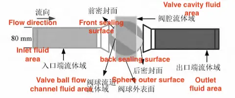
Figure 1 Geometric model of metal double-seal floating ball valve
Table 1: Mesh Division of the Fluid Domain of the Regulating Valve
|
Fluid Domain Area |
Mesh Type |
Mesh Interval |
|
Inlet fluid domain |
Hex/Wedge, Cooper |
8 |
|
Valve cavity fluid domain |
Tet/Hybrid, Tgrid |
8 |
|
Valve ball flow channel fluid domain |
Tet/Hybrid, Tgrid |
8 |
|
Outlet fluid domain |
Tet/Hybrid, Tgrid |
2 |
The complexity of turbulence arises from the multiscale vortical structures within the flow field. The selection of an appropriate turbulence model is critical for accurate turbulence modeling in numerical simulations. The Reynolds-averaged Navier-Stokes (RANS) method is a computational fluid dynamics (CFD) approach based on turbulence statistics. It models turbulence transport and dissipation through closure models, optimizing both computational efficiency and accuracy. Among RANS turbulence models, the eddy viscosity formulation is commonly used due to its strong physical foundation and numerical efficiency. The Realizable k-ε model effectively captures complex flow features, such as rotational effects and three-dimensional flow separation, due to its enhanced treatment of turbulence anisotropy.
For this study, the Realizable k-ε model was selected to address the three-dimensional geometric complexity of the metal double-seal floating ball valve's flow channel. This model balances computational resource limitations with the required accuracy. The flow of the liquid phase is governed by the incompressible RANS equations, which serve as the foundation for analyzing fluid behavior. The momentum conservation equation for the liquid phase is expressed as:

where:
ρ: fluid density
u∗: fluid velocity vector
t: time
p: pressure
μ: dynamic viscosity
f∗: external body force vector
In solid-liquid two-phase flows, the interphase coupling between particles and liquid critically determines flow field topology and particle dynamics. Particle collisions and energy transfer mechanisms further amplify system complexity, introducing combined mechanical, thermodynamic, and hydrodynamic effects under operational conditions. Consequently, this investigation prioritizes the particle momentum equation, interparticle contact forces, and particle-wall collision/rebound modeling.
Erosion is a complex physical process resulting from the interaction between solid particles and material surfaces. This phenomenon can rapidly degrade valve performance, resulting in increased maintenance needs and unscheduled downtime. In industrial systems, solid particle contact and friction with pipeline walls, valves, and other equipment are unavoidable, highlighting the importance of accurately applying erosion models. A thorough analysis of the erosion mechanism enables the development of strategies to mitigate valve wear, improving system reliability and cost-efficiency. Figure 2 illustrates the erosion wear mechanism of typical materials used in metal double-seal floating ball valves.
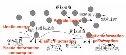
Figure 2 Erosion wear mechanism
As shown in Figure 2, when gas-driven solid particles impact the sealing surface at a specific velocity and angle, they cause plastic deformation of the material surface. Before impact, the particles' kinetic energy is referred to as the total kinetic energy. During impact, a portion of this energy is converted into plastic deformation, resulting in permanent surface deformation. The remaining energy is stored as elastic deformation, corresponding to the material's elastic response. The total kinetic energy (KE) is calculated as follows:

Where m and vᵢ are the mass and collision velocity of the particles, and KEpd and KEed represent the plastic and elastic deformation energies, respectively.
The Oka erosion wear model, developed by Oka et al., is a mathematical model used to predict the erosion wear rate of materials subjected to solid particle impact. It quantifies the erosion wear of pipelines and equipment in high-speed, particle-laden flows. The CFD-DPM model is a multiphysics simulation approach that integrates Computational Fluid Dynamics (CFD) with the Discrete Phase Model (DPM). It simultaneously simulates the continuous and discrete phases of the fluid, making it highly effective for analyzing multiphase flow. Thus, considering the impact angle, velocity, particle size, and material properties, this study uses the CFD-DPM model in ANSYS Fluent to investigate the internal flow field and erosion mechanisms of the ball valve.
An experimental system was developed to study solid-liquid two-phase flow based on the selected computational model and numerical simulation method. The flow characteristics of the metal double-seal floating ball valve during opening and closing were simulated numerically on the existing erosion pipeline experimental platform of a valve company.
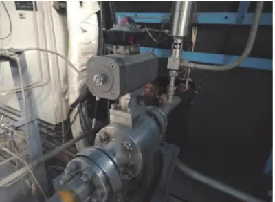
Figure 3 illustrates the erosion pipeline experimental platform. As shown in Figure 3, the valve erosion pipeline experimental platform is an integrated closed-loop system that includes all key components. The system consists of a water tank for continuous water supply, an agitator for uniform medium distribution, a regulating valve for controlling flow rate and pressure, and a centrifugal pump to ensure stable fluid circulation. A flow meter monitors the fluid flow rate.
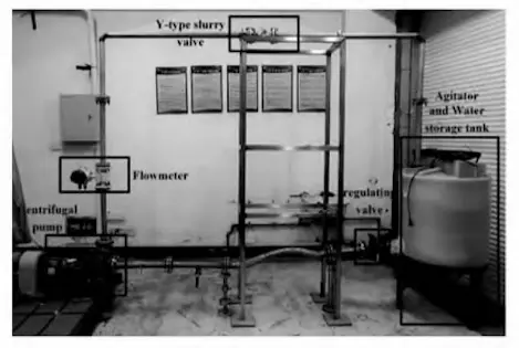
Figure 3 The erosion pipeline experimental platform
The valve model is installed within the pipeline to simulate valve operation and fluid flow under realistic conditions. The system simulates and analyzes valve erosion in high-speed, particle-laden fluids, providing a controlled environment for studying erosion mechanisms and evaluating valve performance.
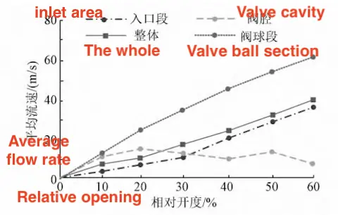
Figure 4 The test results for the partial average flow rate at various relative openings
As shown in Figure 4, the average flow rate in the inlet section, valve ball section, and the overall metal double-seal floating ball valve increases as the relative valve opening increases. As a secondary flow channel, the valve cavity shows a relatively higher flow rate when the relative opening is below 30%. However, once the relative opening exceeds 30%, the flow rate decreases. Within the 10% to 60% relative opening range, the valve cavity's average flow rate does not show a direct proportional relationship with the relative opening. At relative openings of 10% and 20%, the average flow rate in the valve cavity was 11.62 m/s and 13.22 m/s, respectively.
To analyze the effect of valve seat structure on the flow field characteristics, the partial average flow rate of a metal double-seal floating ball valve with various valve seat designs was measured at a 10% relative opening. The test results are shown in Figure 5. As shown in Figure 5, the partial average flow velocity in metal double-seal floating ball valves differs considerably depending on the valve seat structure. At a 10% relative opening, the overall average flow velocities for the O-type, V-type, and T-type valve seats were 20.02 m/s, 11.73 m/s, and 10.16 m/s, respectively. The O-type valve seat features a full-diameter flow channel, which ensures an unrestricted fluid flow path. Thus, at the same relative opening, a ball valve with an O-type valve seat shows a higher partial average flow velocity. In practical operation, the fluid flow in a metal double-seal floating ball valve is significantly influenced by the valve seat structure. Different valve seat designs generate distinct flow patterns and velocity profiles.
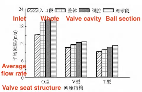
Figure 5 Partial average flow velocity of metal double seated floating ball valve with different valve seat structures
Erosion wear of the metal double-seal floating ball valve is analyzed using the selected computational model and numerical simulation method. The simulation results indicate that when the erosion wear rate exceeds 5 × 10⁻⁴ kg/(m²·s), the service life of the ball valve sealing pair is restricted to six months. Therefore, this study identifies regions where the erosion wear rate exceeds 5 × 10⁻⁴ kg/(m²·s) as high-risk areas. Based on the identified high-risk areas, the variation in the maximum erosion wear rate on the ball valve’s outer surface with different ball structures at varying relative openings is analyzed.
Figure 6 shows that ball valves with different ball structures exhibit minimal change in erosion wear rate within the 10% to 30% relative opening range, suggesting that erosion effects in this range are comparatively low. As the relative opening increases to 30%–50%, the erosion wear rate increases. In the range of 50% to 60%, erosion wear increases most significantly, indicating that an excessive relative opening leads to a rapid rise in erosion wear.
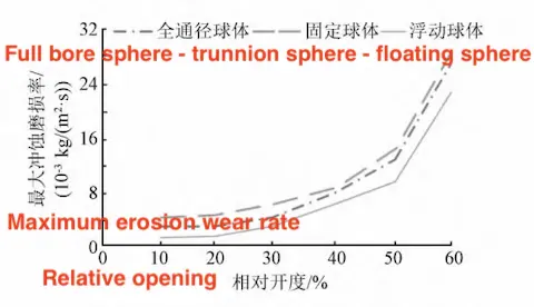
Figure 6 Changes of the maximum erosion wear rate of the outer surface of the ball valve with relative opening
Since the floating ball structure contacts the valve seat on only one side, only a portion of the spherical surface is exposed to fluid in the closed state, reducing overall erosion wear. Thus, compared to full-bore and trunnion-mounted ball structures, the floating ball exhibits the lowest maximum erosion wear rate on the valve's outer surface. These findings offer valuable insights for valve design, supporting structural optimization to mitigate erosion risks and improve durability and reliability.
To provide a theoretical foundation for the design optimization of metal double-seal ball valves, this study employs numerical simulation methods to analyze the flow field characteristics of ball valves with varying structures and their erosion behavior at different relative openings. The experimental results indicate that the valve seat and ball structure significantly influence the flow field characteristics of the ball valve. The O-type valve seat provides lower flow resistance and a more uniform flow velocity distribution due to its full-bore design. In contrast, the throttling behavior of the V-type and T-type valve seats leads to a partial increase in flow velocity near the valve seat, causing flow field disturbances and higher turbulence intensity. The floating ball structure exhibits a lower erosion wear rate under specific operating conditions because only part of the spherical surface is exposed to the fluid. In contrast, trunnion and full-bore balls experience erosion across the entire spherical surface, necessitating more frequent maintenance. V-type and T-type valve seats exhibit higher erosion rates under throttling conditions due to the increased flow velocity and flow field disturbances.
Through in-depth analysis, this study improves understanding of the performance of metal double-seal floating ball valves in industrial applications, providing a scientific basis and technical support for related industries. However, this test was conducted only within the sulfur recovery process environment, and the ball valve flow field and erosion mechanisms in other process environments were outside the scope of this study. Future research could incorporate additional complex process environments into the analysis to enhance the applicability of the findings. Based on the research findings, the influence of the valve seat and ball structure on the internal flow field and erosion should be thoroughly considered during the ball valve design process. The appropriate structure should be selected to minimize erosion and extend the valve’s service life. For applications with high erosion risks, the use of wear-resistant materials and surface treatment technologies should be considered.
Previous: Materials of Soft-Seated Ball Valve Seats
Next: Troubleshooting of Pneumatic Quick-Closing Ball Valves

