Finite Element Analysis of Titanium Floating Ball Valve Seats
Apr 09, 2025
This study investigates a titanium alloy floating ball valve with a nominal diameter of 65 mm. ABAQUS software is used to analyze the shell strength, valve seat sealing, and fatigue life under different operating conditions. The displacement of the ball is controlled to analyze the distribution of sealing pressure on the valve seat and to determine its axial displacement range. The nominal stress method is applied, accounting for the water hammer effect, and fatigue life is evaluated using fe-safe to verify compliance with design specifications.
Under medium pressure, the ball in a floating ball valve shifts toward the valve seat to maintain a reliable seal at the outlet. Under high-pressure conditions, the sealing ring may fail to withstand excessive stress, and the ball is susceptible to misalignment, limiting its application to medium and low-pressure systems. This study examines a titanium alloy floating ball valve with a nominal diameter of 65 mm. The key components consist of the valve body, ball, valve seat assembly, valve stem, O-ring, and fasteners. The handwheel rotates the valve stem, which in turn rotates the ball by 90° around the valve stem axis, allowing the valve to open and close (Figure 1).
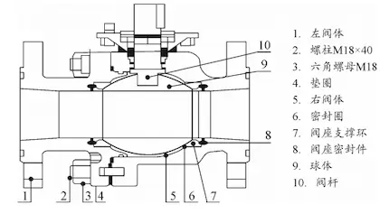
1. Left valve body 2. Stud M18×40 3. Hexagonal nut M18 4. Washer 5. Right valve body 6. Sealing ring 7. Valve seat support ring 8. Valve seat seal 9. Ball 10. Valve stem
Figure 1 Floating ball valves
The valve seat has a piston-like structure, with one valve seat installed in each of the two coaxial openings in the valve body. An O-ring is placed at the bottom of the valve seat. Initially, the valve seat is compressed by the elastic force of the O-ring, ensuring a tight seal with the ball. The surface of the sealing seat undergoes plastic deformation, creating a seal under a small pressure differential. When the ball valve is closed, the ball moves along the pipeline axis due to the combined elastic force of the O-ring and the pressure from the medium, establishing a tight seal with the valve seat at the outlet. The installation of valve seats at both ends allows reverse pressure to maintain the seal, ensuring two-way sealing functionality.
In practical engineering, although the ball and valve seat sealing surfaces are precisely machined with high levels of roughness and roundness, they remain uneven at the microscopic level, with grooves present. External force is needed to generate a specific pressure between the valve seat sealing surface and the ball to ensure a proper seal. The pressure applied per unit area of the sealing surface is referred to as the sealing pressure ratio, which is a critical parameter for ensuring a reliable seal. The required sealing pressure ratio is the minimum value necessary to ensure a proper seal. The ball valve's sealing pressure ratio must comply with formula (1).
![]()
qmf represents the required sealing pressure ratio; q is the actual sealing pressure ratio, and [q] is the allowable sealing pressure ratio of the sealing surface material. The required sealing pressure ratio can be calculated using the empirical formula from 'Ball Valve Design and Selection,' as shown in formula (2).

m is the correlation coefficient of the medium; a and C are the correlation coefficients of the sealing surface; P is the working pressure of the fluid, and 6 is the projection width of the sealing surface in the direction perpendicular to the fluid flow. The theoretical formula for calculating the sealing pressure ratio is given in formula (3).

Dmw is the outer diameter of the valve seat and Dnw is the inner diameter of the valve seat. Substituting the data, the results are qmf = 11.96 MPa and q = 13.54 MPa. The allowable specific pressure for polytetrafluoroethylene is [q] = 20 MPa. From a theoretical standpoint, the sealing specific pressure satisfies the condition qMF < q < [q], indicating that the ball valve's sealing performance is acceptable.
However, the formula used for the theoretical calculation of sealing specific pressure is an empirical one and is not entirely accurate. Additionally, the calculation result represents the average sealing specific pressure and does not reflect the spatial distribution of the pressure. Therefore, it is crucial to conduct finite element analysis on the sealing performance of the ball valve and analyze the distribution of sealing pressure on the sealing surface.
The analysis examines the sealing performance between the ball and valve seat when the valve is closed. The model consists of the ball, valve seat support ring, and sealing ring, as illustrated in Figure 2. The model is divided into 113,688 grids, with sizes ranging from 2 to 4 mm. Figure 2 shows the simplified model for the ball valve sealing analysis. The ball and seat support ring are composed of titanium alloy TA31, with a density of 4.5 g/cm³, Poisson’s ratio of 0.32, Young’s modulus of 105,000 MPa, and yield strength of 785 MPa. The sealing ring is made of PTFE (polytetrafluoroethylene), with a density of 2.2 g/cm³, Poisson’s ratio of 0.45, Young’s modulus of 500 MPa, and yield strength of 23 MPa. Elastic contact is applied between the ball and the sealing ring, with the interaction discretized using the surface-to-surface method. The main surface is assigned to the ball, while the secondary surface is assigned to the sealing ring, as the ball has high stiffness and the mesh is coarse, which aids in model convergence. The contact properties are defined as follows: the tangential behavior uses the "valve" method with a friction coefficient of 0.35, and the normal behavior is defined as "hard" contact.
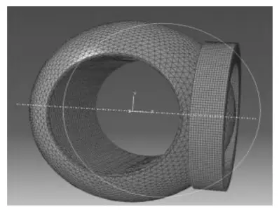
Figure 2 Simplified model for ball valve sealing analysis
Currently, there are two primary methods for applying loads in the finite element analysis of ball valve sealing. The first method involves directly applying the load to the valve seat’s end face, as used by Yongliang Liu , Wei Wang, and others. The second method applies the load by adjusting the displacement of the valve seat, as implemented by Jiasheng He and his team. The sealing performance of the ball valve examined in this study primarily results from the compression of the O-ring. Due to the difficulty in precisely determining the load size and distribution, the second loading method is employed. However, unlike Jiasheng He's study, this research focuses on a floating ball valve, where the sealing mechanism involves the valve seat being fixed while the ball moves toward it, pressing against the sealing ring to create a seal. Therefore, the analysis should focus only on the sealing performance between the outlet end of the ball and the valve seat. To better simulate the actual working conditions of the floating ball valve, the outlet end valve seat is fixed, and axial displacement is applied to the ball. Full constraints are applied to both the end and outer surfaces of the valve seat, while an axial displacement load (AL) is applied to the ball. Additionally, a pressure of 7.2 MPa is applied to the side of the ball exposed to the medium's thrust. To examine the impact of ball displacement on the sealing pressure ratio, this paper defines 10 loading conditions, ranging from AL = 0.1 mm to AL = 1.0 mm. In the stress distribution diagram, a radial node path along the sealing surface is selected, and the corresponding stress values along this path are extracted for analysis.
For example, consider AL = 0.1 mm to analyze the distribution of the partial sealing pressure ratio along the radial nodes of the sealing surface (Figure 3). The sealing pressure ratio distribution diagram for AL = 0.1 mm in Figure 3 shows that the highest local sealing pressure ratio is found on the inner side of the valve seat. This is due to the type 1 structure of the valve seat support ring, which prevents the sealing ring from laterally deforming during compression, resulting in good sealing performance between the valve seat sealing ring and the ball. Additionally, the sealing ring is highly susceptible to crushing. The partial sealing pressure ratio decreases from the inner side of the valve seat to the center of the sealing ring, while it gradually increases from the center to the outer side of the valve seat, resulting in a pressure distribution with lower pressure at the center and higher pressure at the ends. This issue arises from the extrusion deformation of the sealing surface. As a result, the sealing pressure ratio at the outer end of the valve seat gradually decreases. This occurs because the extrusion deformation prevents the ball from establishing a proper contact with the sealing surface, leading to a loss of sealing effectiveness near the outer side of the valve seat. The ball valve discussed in this article is made of polytetrafluoroethylene (PTFE). During the sealing process, a small gap exists between the outer diameter of the sealing ring and the valve body, while the end face of the sealing ring is fixed to the valve seat and cannot move. As the ball displaces along the valve axis, the axial deformation of the inner diameter of the sealing ring is smaller compared to the middle section, resulting in a larger extrusion force.
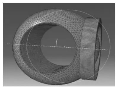
Figure 3 Sealing pressure distribution cloud diagram when ΔL = 0.1 mm
The axial deformation of the middle section of the sealing ring is relatively large, resulting in a smaller extrusion force. Additionally, during the sealing process, despite the close contact between the ball and the sealing ring, the presence of the fluid medium leads to a capillary effect. As a result, a thin layer of fluid remains between the ball and the sealing ring at the contact point. During the relative movement of the ball pressing against the valve seat, the contact between the ball and the sealing ring becomes tighter, causing the fluid medium between the outer diameter and the middle of the sealing ring to gradually decrease. Under the combined effect of the ball's displacement and the fluid medium, the sealing pressure ratio at the outer diameter of the sealing ring is slightly higher than at the middle part of the sealing surface. In the circumferential direction, the stress on each annular surface is uniform, so the overall sealing pressure ratio remains relatively unchanged. However, considering the combined effects of pipeline tensile bending stress, medium pressure, bolt preload, and other factors, the sealing pressure ratio fluctuates along the circumferential direction. The relationship curve between the ball displacement load (AL) and the sealing pressure ratio is shown in Figure 4.
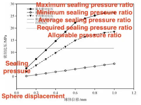
Figure 4 Relationship curve between sealing pressure ratio and ball displacement
It can be observed that when the axial displacement of the ball exceeds 0.45 mm, the average sealing pressure ratio satisfies the sealing requirements. When the axial displacement of the ball exceeds 0.6 mm, the sealing pressure ratio becomes excessive, surpassing the allowable limits of the sealing surface material, which can lead to damage of the sealing ring. Therefore, by controlling the axial displacement of the ball between 0.45 and 0.60 mm, both the ball and the valve seat maintain optimal sealing performance, while avoiding damage to the sealing ring caused by an excessive sealing pressure ratio.
(1) The radial distribution of the sealing pressure ratio on the sealing surface follows this pattern: near the inner side of the valve seat, the sealing pressure ratio is high; at the center of the sealing surface, it is lower; and near the outer side of the valve seat, it is slightly higher than in the middle. This distribution results from the extrusion deformation of the soft sealing material and the capillary effect.
(2) Maintain the axial displacement of the ball between 0.45 and 0.60 mm to ensure optimal sealing performance between the ball and the valve seat, while preventing damage to the sealing ring from excessive pressure.
During repeated opening and closing cycles, the ball valve is subjected to fluctuating medium pressure, which results in the formation of cracks or crack clusters that gradually propagate, ultimately leading to the failure of structural components. This type of damage is referred to as fatigue failure of the ball valve. The stress level that causes fatigue damage is lower than the yield strength. To ensure that the ball valve performs its intended function within its service life, it is essential to analyze its fatigue life to prevent fatigue failure during the specified operational period.
(1) Process: The finite element analysis (FEA) process for the ball valve consists of the following steps:
Ball valve drilling structure
Finite element modeling
Mesh generation
Static analysis
Contact interaction
Load and boundary constraints
Fatigue life analysis
Fatigue life evaluation of critical components
(2) Methods: The primary methods for fatigue life analysis include the nominal stress method, partial stress-strain method, energy method, damage mechanics method, and stress-strain field intensity method. The nominal stress method is based on the material’s S-N curve (stress-life curve).
The fatigue life is determined by incorporating the stress concentration factor and nominal stress of critical areas in the specimen or structure with fatigue damage theory. The fundamental assumption is that if a component experiences the same stress system effects and load spectrum, its fatigue life will be identical. The advantage of this method is that it accounts for the effects of load sequence and residual stress while remaining simple and easy to apply. The partial stress-strain method is based on the material’s E-N (strain-life) curve. The partial stress at the notch is analyzed using the nominal stress history of the structure, and fatigue life is determined by applying linear cumulative damage theory. The basic assumption is that the fatigue life of a component is the same when the stress-strain history of its critical regions is identical. Since the E-N curve is derived under controlled strain test conditions, there is limited test data available. This paper employs the nominal stress method for fatigue analysis.
When the inner wall of the water pipe is smooth and the flow is steady, a rapid valve opening can cause the water flow to exert pressure on the valve, generating a shock wave in the flow and resulting in a water hammer effect. The water pressure generated by the water hammer effect can reach several to dozens of times the working pressure, resulting in significant destructive force. This paper conducts a fatigue analysis of the ball valve under the water hammer effect, using approximately 20 times the working pressure (100 MPa) and an axial displacement of 0.4 mm. The load is a pulsating cyclic load with a load ratio of R = 0. The impact force from the water flow primarily acts on the sphere. The model is identical to the sealing model, with the end face and outer side face of the sealing seat fully fixed. The sphere and sealing surface are modeled with 'face-to-face contact,' where the contact properties are defined as tangential 'penalty' contact and normal 'hard' contact. A pressure of 100 MPa is applied to the left side of the sphere to simulate the impact force from the water flow. The results of the static analysis are shown in Figures 6 to 8. With a water pressure of 100 MPa, the maximum stress in the ball is 83.4 MPa, the maximum stress in the seal ring is 30.1 MPa, and the maximum stress in the support ring is 340.7 MPa. The analysis results indicate that the stress at the variable cross-section of the support ring is the highest, marking it as the critical area. The ABAQUS analysis results were imported into fe-safe, where fatigue analysis was conducted using the nominal stress method and the Goodman mean stress correction formula. The minimum fatigue life of the support ring is 88,245 cycles, which exceeds the required fatigue life of 2,000 cycles.
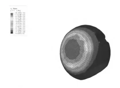
Figure 5: Sphere stress distribution contour plot
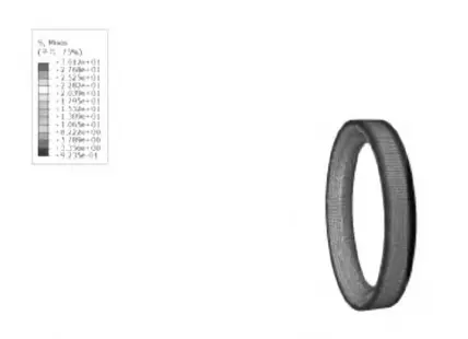
Figure 6: Seal stress distribution contour plot
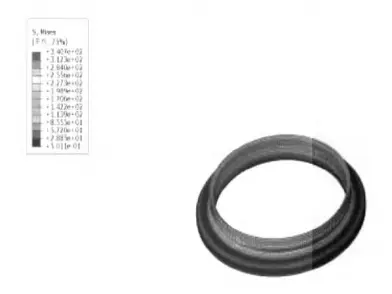
Figure 7: Ring stress distribution contour plot
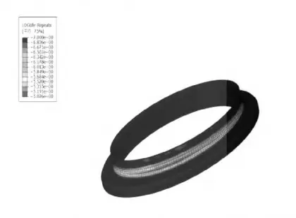
Figure 8: Support ring fatigue life contour plot
Based on the mechanism of fatigue wear, the fatigue life of the ball valve can be enhanced by preventing component cracking or crack propagation.
Extend the ball valve closing time. The impact force generated by the water hammer effect is directly influenced by the valve closing time. By appropriately extending the closing time, the water flow impact force will be significantly reduced, which in turn minimizes ball deformation and the pressure differential during valve operation.
Improve residual stress. Residual tensile stress typically decreases the component's fatigue life. However, when residual compressive stress is present on the ball valve's surface, its fatigue strength is enhanced. During the manufacturing process, residual stress on the ball valve's surface can be improved through processes such as quenching, cold working, and hardening, thereby increasing its fatigue life.
A rougher surface on the ball valve increases its sensitivity to stress concentration, making it more susceptible to fatigue damage. Surface roughness should be minimized in areas with high stress concentration, such as grooves, fillets, and variable sections.
(1) The three-dimensional model of the ball valve is simplified, and the sealing performance of the valve seat is analyzed under a displacement load. The radial distribution of the sealing pressure ratio along the sealing ring is obtained, showing a smaller value in the center and larger values at both ends. A relationship curve between the displacement load and the valve seat sealing pressure ratio is also generated. The simulation results indicate that when the axial displacement of the ball is controlled between 0.45 and 0.60 mm, the sealing performance of the valve seat satisfies the design specifications.
(2) Fatigue analysis is performed using the nominal stress method in fe-safe, accounting for the water hammer effect. The critical area of the ball valve is located at the variable cross-section of the support ring. The minimum fatigue life of the support ring is 88,245 cycles, meeting the required fatigue life standards.
Previous: Troubleshooting of Pneumatic Quick-Closing Ball Valves
Next: Design of a Quality Test Method for Underwater Directional Control Valves

