Electric Valves Stem Troubleshooting
Aug 04, 2024
On this page
In the petroleum and petrochemical industry, electric valves have become indispensable and important equipment in engineering projects. At the same time, problems in the design, operation, maintenance, and other aspects of electric valves have also arisen, attracting widespread attention in the industry. To avoid the problems of stem fracture of electric actuated valve, mismatch between actuator and valve body, and actuator selection, in addition to summarizing and analyzing the causes of failure, it is necessary to strictly control the design selection, raw material procurement, production process, and factory inspection stage to solve the problem from the source. The above measures are currently effective methods that can avoid various accidents and delays in production during operation as much as possible. Originally, the main discussion was on the problem of stem fractures.
With the development of the economy and the advancement of social science and technology, the use of industrial electric valve is becoming increasingly extensive. The high degree of automation has made electric valves a mainstream facility in modern industry. However, fault control of electric valves remains a difficult problem to overcome in various fields. Therefore, analyzing and summarizing industrial electric valve failures is crucial. Common faults of industrial electric valve are shown in Table 1.
Table 1 Summary of electric valve failures
Table 1 Summary of electric valve failures
| Items | Failure description |
| 1 | Wrong actuator selection |
| 2 | Deformed or broken valve stems |
| 3 | Inaccurate valve limit setting |
| 4 | Small protection torque value |
| 5 | Torque parameter mismatch |
| 6 | Deformed and fallen valve seat seal rings |
| 7 | Valve chamber scales |
| 8 | Poor lubrication of actuators |
| 9 | Damaged electrical components |
| 10 | Failures of drive copper sleeves |
The following is a detailed analysis of actuator selection and the valve stem fracture.
The valve stem at the flange connection between the electric valve body and the electric actuator is broken, with the thread spacing at the fracture being larger than at other parts of the valve stem. The valve stem fracture is located at the root of the fourth thread. The fracture is star-shaped and convex, with a gray color and an uneven surface. No obvious corrosion or metallurgical defects visible to the naked eye were found on the fracture. There are obvious traces of contact damage on the thread (Figure 1). The thread dimensions were measured, and the fracture area exhibited a necking, indicating that the valve stem underwent elongation deformation. (Figure 2).
Table 2 Chemical composition analysis values
Table 2 Chemical composition analysis values
| Elements | C | Si | Mn | P | S | Cr |
| Test value | 0.186 | 0.446 | 0.505 | 0.019 | 0.005 | 12.46 |
| GB/T 1220 | 0.16 - 0.25 | ≤1.0 | ≤1.0 | ≤0.040 | ≤0.030 | 12.00 - 14.00 |
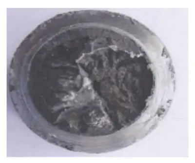
Figure 1: Fracture morphology
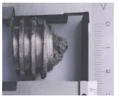
Figure 2: Deformation morphology
The chemical composition of the sample was analyzed using the American PE 2100DV ICP emission spectrometer and a carbon sulfur analyzer, as shown in Table 2.
Table 3 Mechanical properties test report
Table 3 Mechanical properties test report
| Items | Rp0.2 (MPa) | Rm (MPa) | A (%) | Z (%) | Hardness value (HBW) | AKu2 (J) |
| Test values | 637 | 806 | 22.0 | 62 | 246, 249 and 250 | 52, 43 and 53 |
| GB/T 1220 | ≥440 | ≥640 | ≥20 | ≥50 | ≥159 | ≥63 |
The sample was taken from the valve stem for testing tensile properties, impact properties, and hardness. The tensile properties and hardness values met the requirements, but the impact properties were lower than the standard requirements.
The fracture sample was placed under a scanning electron microscope for observation, revealing the low-power morphology (see Figure 3). After magnification, the middle part of the fracture showed intergranular and dimple characteristics (see Figure 4), and there was a shear lip on the edge of the fracture, exhibiting dimple characteristics (see Figure 5).
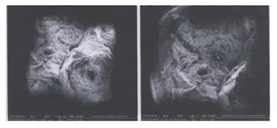
Figure 3: Morphology of the middle and edge of the fracture
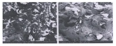
Figure 4: Morphology of the middle of the fracture
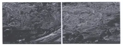
Figure 5: Morphology of dimples at the edge of the fracture

Figure 3: Morphology of the middle and edge of the fracture

Figure 4: Morphology of the middle of the fracture

Figure 5: Morphology of dimples at the edge of the fracture
The fractured specimens were cut along the axis of the circle center and observed under a metallographic microscope after polishing. The fracture was sawtooth-shaped with many secondary cracks (see Figure 6). The thread root position at the edge of the fracture was damaged (see Figure 7). No processing defects were found in the thread morphology of other areas or the thread root morphology, and no material metallurgical defects were found on the fracture.
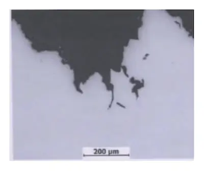
Figure 6 Fracture morphology
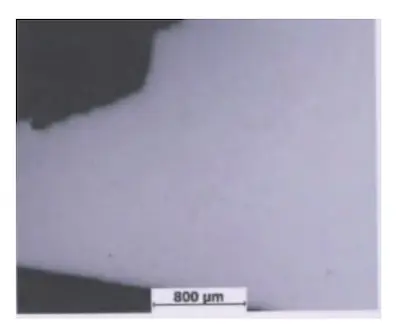
Figure 7 Thread root morphology

Figure 6 Fracture morphology

Figure 7 Thread root morphology
After the specimen was eroded, the metallographic structure at the fracture was the same as in other parts, all of which were tempered troostite and carbides distributed in a network (see Figure 8). There was no deformation at the thread root fracture (see Figure 9).
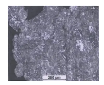
Figure 8 Metallographic structure at the fracture
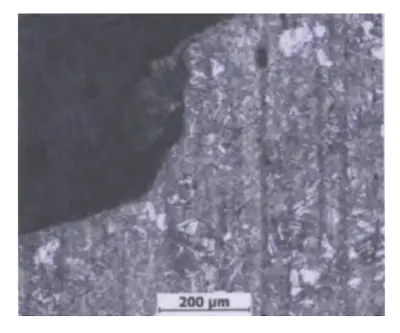
Figure 9 Thread root fracture

Figure 8 Metallographic structure at the fracture

Figure 9 Thread root fracture
In summary, the chemical composition, tensile properties, and hardness of the valve stem meet the requirements of national standards, but the impact properties are lower than the standard requirements. The strength of the valve stem is too high, the toughness is insufficient, and the brittleness of the material reduces the impact resistance of the valve stem to a certain extent.
The metallographic structure of the valve stem shows segregation, with carbides arranged in a network along the axial direction. No other anomalies or metallurgical defects were found. The fracture of the valve stem is "mountain"-shaped, with the fracture site located at the root of the fourth thread from the screw. The fracture surface is dark, and no visible metallurgical defects or corrosion were found. There is obvious shrinkage deformation at the fracture, and collision damage is evident on the thread. The center of the fracture exhibits grain and dimple features, while the edge shows the shear lip of the dimple. The fracture morphology is similar to that of a tensile fracture. Metallographic analysis reveals no processing defects, microcracks, slag inclusions, or other defects at the root of the thread.
In summary, the fracture of the valve stem is an overload fracture caused by a large external force.
Table 4 Comparison of torque value between valve stems and actuators
| Valve stem torque values | Electric actuator data values | ||||
| Valve models | Maximum bearing torque of valve stems | Valve operation torque | Original rated torque | Torque protection range | Torque protection range values |
| DN150 - 25 | 320 N • m | 90 N • m | 250 N • m | 40 to 120% | 100 to 300 |
| DN100 - 100 | 400 N • m | 150 N • m | 400 N • m | 40 to 120% | 160 to 480 |
Previous: An Introduction to Control Valves
Next: Selection of Electric Actuators

