Dynamic Water Closing Test of Ball Valve in High-Head Pumped Storage: Performance Analysis
Apr 28, 2025
Abstract: The ball valve, a critical component in the pumped storage power station unit, is installed between the pressure steel pipe and the volute to prevent accidents caused by guide vane failure. This study tests the dynamic water closing ability of the ball valve under idling, 50% rated load, and 100% rated load conditions, measuring parameters such as unit swing, valve vibration, relay oil pressure, and the pressures at the valve front and volute. The results show that the ball valve reliably closes and cuts off water flow without causing harmful deformation or damage to the valve and related equipment, even when the guide vane fails to close.
Guided by the national dual carbon goals, new energy has entered a phase of large-scale development and utilization. Pumped storage power stations, recognized as the most reliable, economical, and technologically mature energy storage devices in the power system, are experiencing a historic opportunity for rapid growth. As pumped storage power stations expand, pumped storage units are evolving toward higher heads, higher speeds, and larger capacities. The Changlongshan Pumped Storage Power Station, with a rated speed of 500 r/min and a maximum head of 756 m, ranks first in China and second in the world. The Guangzhou Pumped Storage Power Station, with a total installed capacity of 2,400 MW, is the largest pumped storage power station in the world. However, due to the late development of pumped storage power stations in China, along with the complex operating conditions and frequent start-stop cycles of pumped storage units, the pressure on ensuring the safe and stable operation of these units remains high.
The ball valve plays a critical role as auxiliary equipment in pumped storage power stations. Installed between the pressure steel pipe and the volute, its stability and reliability are vital for the safety of the entire underground plant. To prevent failure of the unit’s speed control system, which could leave the guide vane unable to close and cut off the water flow during shutdown, the ball valve must have an emergency dynamic water shut-off function. This ensures that the unit does not experience uncontrolled runaway conditions, helping to prevent the escalation of accidents.
According to GB/T 14478-2012, "Basic Technical Conditions for Inlet Valves of Large and Medium-Sized Turbines," Section 4.3 explicitly states that the inlet valve must be capable of closing dynamically under any unit operating condition, without causing harmful vibrations. Therefore, the dynamic water closing function of the ball valve in emergency and special circumstances is critical to ensuring the safe and reliable operation of the hydropower unit. This paper tests and analyzes key parameters, including unit oscillation, ball valve vibration, relay oil pressure, and the pressures at the valve front and volute. The dynamic water closing test is conducted at idling, 50% rated load, and 100% rated load to ensure that the ball valve can reliably cut off water flow when the guide vane fails to close and that the valve and related equipment do not suffer harmful deformation or damage.
The power station is equipped with four 300 MW mixed-flow reversible units, with an average annual power generation of 18.36 × 10⁶ kWh and an annual pumping power consumption of 24.09 × 10⁶ kWh. The rated speed is 428.6 r/min, and the rated head is 410 m. The inlet valve features a double-sealed hydraulic ball valve, and the layout consists of a one-tunnel-two-unit configuration. The diversion tunnel is 1331.35 m long, and the tailwater tunnel measures 1071.44 m. The main equipment parameters, including those for the pump turbines, generators/motors, and ball valves, are shown in Table 1.
Table 1 Main equipment parameters
|
Item |
Index |
|
Type |
Vertical shaft, single-pole mixed flow reversible |
|
Model |
HINA1411-1J-410 |
|
Impeller diameter (mm) |
4104 |
|
Suction height (m) |
-65.0 |
|
Pump rated speed (r/min) |
428.6 |
|
Turbine rated head (m) |
410.0 |
|
Turbine rated output (MW) |
306.1 |
|
Turbine rated flow (m³/s) |
83.96 |
|
Pump maximum gross head (m) |
449.5 |
|
Pump minimum gross head (m) |
416.0 |
|
Pump maximum output (MW) |
320.0 |
|
Type |
Reversible synchronous generator/motor |
|
Model |
SFD300-14/6700 |
|
Required capacity (MVA) |
334 |
|
Generator rated power (MW) |
300 |
|
Motor rated electric power (MW) |
322 |
|
Rated frequency (Hz) |
50 |
|
Rated voltage (kV) |
10 |
|
Cyclic voltage range (kV) |
18 ± 5% |
|
Moment of inertia (t•m²) |
5750 |
|
Type |
Double seal hydraulic ball valve |
|
Rated working oil pressure (MPa) |
6.3 |
|
Design pressure (MPa) |
7.2 |
|
Ball valve maximum net water head (m) |
514.5 |
|
Relay diameter (mm) |
500 |
|
Number of relays |
2 |
|
Ball valve opening time (s) |
40–100 |
|
Ball valve closing time (s) |
40–100 |
The test measuring points for the unit primarily include active power, speed, guide vane opening, upper guide, lower guide, water guide bearing X/Y direction swing, upper frame, lower frame, top cover horizontal and vertical vibration, volute inlet pressure, tailwater inlet pressure, and other parameters. The layout of the unit test measuring points is shown in Figure 1.
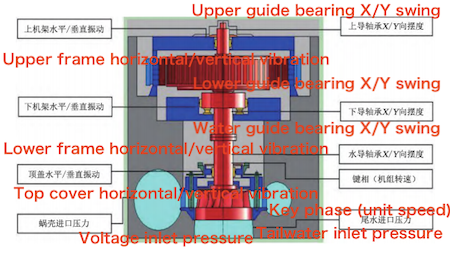
Figure 1: Measuring Point Layout of the Unit Test
The test measuring points for the ball valve primarily include the ball valve front pressure, steel pipe pressure, ball valve relay opening and closing cavity pressure, relay stroke, ball valve upstream, body, base, downstream horizontal and vertical vibration, ball valve base, expansion joint displacement, and other parameters. The layout of the ball valve test measuring points is shown in Figure 2.
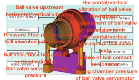
Figure 2: Measuring Point Layout of Ball Valve Tests
The test data acquisition system uses the TK2120A portable power (waveform) recorder and analyzer, as well as the TTS332 dynamic signal test and analysis system. The unit speed, upper guide, lower guide, water guide swing, and ball valve displacement signals are measured using the Bently 330180 system. Vibration signals from the upper frame, lower frame, top cover, and upstream, downstream, body, and base of the unit are collected by the LVS10 low-frequency vibration sensor. All these signals are connected to the TTS332 dynamic signal test and analysis system.
The volute inlet pressure, tailwater inlet pressure, pressure in the steel pipe, ball valve closing cavity pressure, and ball valve opening pressure are measured by the ST3000 pressure transmitter. The relay stroke is measured using the MPS pull-rope displacement sensor. The guide vane opening is connected to the data acquisition system by linking the speed governor guide vane opening signal in series. Active power is calculated by measuring the machine-side TV and TA signals, and the unit frequency is calculated by measuring the machine-side TV signal. All of these signals are connected to the TK2120A portable power (waveform) recording and analysis instrument. The on-site installation of the test equipment is shown in Figures 3 and 4.
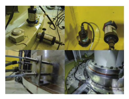
Figure 3: Photo of On-site Installation of Unit Vibration Equipment
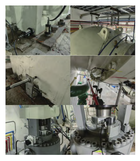
Figure 4: On-site Installation of Ball Valve Vibration, Displacement, and Pressure Measuring Equipment
- The ball valve must reliably close and shut off the water flow when the guide vane is not closed, and the ball valve closing time must meet the design requirements.
- During the dynamic water closing process of the ball valve, no excessive vibration should be generated in any part of the ball valve, and no harmful deformation or damage should occur to the ball valve or related equipment.
- During the dynamic water closing test, the maximum pressure at the centerline of the volute inlet should not exceed 7.2 MPa, and the minimum pressure should not fall below 3 MPa; the maximum pressure at the tailwater inlet should not exceed 1.4 MPa, and the minimum pressure should not fall below zero. The unit speed increase rate should not exceed 45% of the rated speed.
The dynamic water closing test of the ball valve is a destructive test that will cause some damage to the ball valve body, the unit, and the water diversion tunnel. Additionally, since the plant elevation is below the water level of the lower reservoir, an accident could easily lead to flooding of the plant. Therefore, thorough preparations must be made before the test.
a. Conduct a static water test on the ball valve before the dynamic test. Ensure that the ball valve’s opening and closing times meet the design requirements, that the ball valve and guide vane are properly closed, and verify the normal functioning of the guide vane and ball valve hydraulic circuits. Confirm that the water levels of the upper and lower reservoirs meet the test requirements, and develop an emergency plan for potential test accidents, including clear escape routes.
b. Ensure that the relevant public systems of the test unit are operating normally. Verify that the control circuit operates correctly when the unit is shut down due to an emergency, and that the water, electrical, and other protections of the test unit are reliable and functioning correctly. The accident start signals that could affect the test must be removed, such as abnormal closure of the ball valve, comprehensive tripping of the swing, reverse power protection, etc.
c. Test equipment and instruments should be strictly calibrated, and the pressure measuring pipelines should be vented before starting. After the test begins, check the signal data from all measuring points to ensure that the collected test data is accurate and valid.
d. Non-test units must be in a shutdown state. Ensure that the test site has clear access roads, sufficient lighting, and that all non-essential personnel have left the area. Unauthorized personnel and vehicles must be prohibited from entering the test site. The doors and windows of the upper reservoir hoist and shut-off machine room should be open, and the water diversion pressure regulating well and tailwater pressure regulating well doors should be open. A designated person must be on duty at the upper reservoir gate to ensure it can be closed quickly if the guide vane and ball valve fail to close during the test.
e. During the test, the test personnel will use industrial television and a monitoring system to track the key equipment parameters of the unit, including the ball valve, waterwheel room, and bearing temperature. If water accumulation is found in the waterwheel room, the bearing temperature rises suddenly, or vibration levels become excessive, the unit should be shut down immediately for inspection.
The ball valve’s dynamic water closing test consists of a static test and a dynamic test. The dynamic test is conducted under three operating conditions: idling, 50% rated load, and 100% rated load.
Under static water conditions, the guide vane is kept fully closed, the relay lock is engaged, and the mechanical brake is applied. The ball valve is in the fully open position. The guide vane fully closed signal is short-circuited in the ball valve control cabinet, and the solenoid valve coil plugs on the ball valve working seal engagement side and the ball valve fully closed position hydraulic lock engagement side are removed. Press the ball valve closing button on the monitoring system to ensure that the ball valve can close normally, and that the ball valve working seal and relay lock are not engaged.
The unit is automatically started and allowed to run stably for 15 minutes under idling, 50% rated load, and 100% rated load conditions, respectively. The relevant equipment of the unit is then checked and confirmed to be operating normally. The guide vane fully closed signal is short-circuited in the ball valve control cabinet, the speed governor is switched to "local" and "manual" control modes, and the guide vane opening is kept unchanged. The solenoid valve coil plugs on the ball valve working seal engagement side and the ball valve fully closed position hydraulic lock engagement side are pulled out.
Under the monitoring system, the button to close the ball valve is pressed to conduct a dynamic water closing test. After the ball valve is closed, the emergency shutdown button is pressed to check whether the guide vane is closed and to verify the execution of the unit shutdown process. The dynamic water closing process curves of the ball valve under idling, 50% rated load, and 100% rated load conditions are shown in Figures 5 to 7.
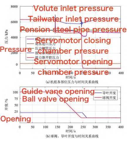
(a) Curves of the relationship between the ball valve and guide vane opening and time
(b) Curves of the relationship between the pressure and time of each part of the unit
Figure 5 Dynamic water closing process curve of the ball valve under idling conditions
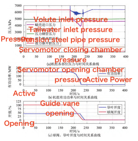
(a) The relationship curve between pressure and time in each part of the unit
(b) The relationship curve between active power and time of the unit
(c) The relationship curve between ball valve and guide vane opening and time
Figure 6 Dynamic water closing process curve of the ball valve under 50% rated load conditions
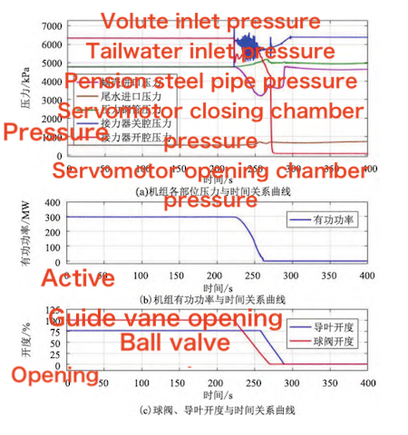
(a) The relationship curve between pressure and time in each part of the unit
(b) The relationship curve between active power and time of the unit
(c) The relationship curve between ball valve and guide vane opening and time
Figure 7 Dynamic water closing process curve of the ball valve under 100% rated load conditions
Under the test conditions, the unit ball valve can reliably cut off the water flow without closing the guide vane, and no significant damage or harmful deformation occurs. The dynamic water closing test data of the ball valve are analyzed as follows:
a. Idling conditions: The ball valve fully closes in 51.59 seconds. The expansion joint downstream of the ball valve displaces by 0.016 mm. The maximum closing chamber pressure of the ball valve servo is 6.929 MPa. The minimum inlet pressure of the volute is 4.167 MPa, which is less than 7.2 MPa. The minimum inlet pressure of the tailwater pipe is 0.739 MPa, which is greater than zero, meeting the calculation requirements for regulation guarantees.
b. 50% rated load condition: The ball valve fully closes in 50.54 seconds. The expansion joint downstream of the ball valve displaces by 0.061 mm. The maximum closing chamber pressure of the ball valve servo is 6.954 MPa. The minimum inlet pressure of the volute is 3.868 MPa, which is less than 7.2 MPa. The minimum inlet pressure of the tailwater pipe is 0.674 MPa, which is greater than zero, meeting the calculation requirements for regulation guarantees.
c. 100% rated load condition: The ball valve fully closes in 48.56 seconds. The expansion joint downstream of the ball valve displaces by 0.136 mm. The maximum closing chamber pressure of the ball valve servomotor is 6.985 MPa. The minimum inlet pressure of the volute is 3.222 MPa, which is less than 7.2 MPa. The minimum inlet pressure of the tailwater pipe is 0.588 MPa, which is greater than zero, meeting the calculation requirements for regulation guarantees.
During the dynamic water closing process of the ball valve, the swing of the ball valve and the unit increased significantly. In the dynamic water closing process of the ball valve under 50% rated load and 100% rated load conditions, the swing of the upper and lower guides exceeded the alarm value.
a. During the dynamic water closing process of the ball valve, the unit speed did not increase. The steel pipe pressure increased initially and then decreased, but the increase was minimal. The volute inlet pressure and the tailwater inlet pressure both decreased initially and then increased. The displacement of the expansion joint of the ball valve was noticeable.
b. As the test load increased, the vibration of the unit and the ball valve increased significantly during the dynamic water closing process. The unit swing exceeded the alarm value but did not reach the trip value.
c. The dynamic water shutoff test of the ball valve under idling, 50% rated load, and 100% rated load conditions confirmed that the unit’s ball valve can reliably cut off the water flow without closing the guide vane. No significant damage or harmful deformation occurred, demonstrating that the ball valve has good dynamic water shutoff capability.
Previous: Design of a Quality Test Method for Underwater Directional Control Valves
