Designing High-Pressure Cryogenic Ball Valves for LNG Devices
Nov 02, 2024
On this page
The high-pressure, large-diameter cryogenic ball valves used for controlling the high-pressure delivery pump process system at the LNG receiving station operate under extremely harsh conditions: ultra-low temperature (-162°C) LNG, a design pressure of 16.0MPa, full pressure differential for opening and closing, and frequent operational cycles. It is one of the key pieces of equipment in the LNG receiving station system. It must not only have a long service life and be safe and reliable, but it also cannot be disassembled once installed on the pipeline, and any sealing leakage failures must be repairable online. To this end, technical research must address various aspects, including product structure design, material selection and processing, and manufacturing accuracy, to meet the high-performance and longevity requirements of the entire valve assembly. The application of LNG in China began relatively late, and many unknown technical fields necessitate extensive experiments and tests to understand its characteristics. Numerous technical challenges require dedicated research and development to achieve breakthroughs.
Top-mounted ball structure with sleeve welding and a sleeve length of 100 mm, bidirectional sealing, with the valve cavity automatically releasing pressure to the high-pressure upstream end of the DIB-2 structure; under design conditions, the normal temperature seal has no leakage, while the low-temperature leakage rate is ≤33 × DN/1000 ml/s. In both normal and low-temperature environments, the valve cavity discharge pressure is 1.06 to 1.25 times the working pressure. The long-necked valve cover design meets the packing requirements in environments above 0°C. For normal and low-temperature pressure shell connections, helium leak detection shows a micro leakage rate of ≤1.78 × 10⁻⁷ mbar·L/s·mm. For normal and low-temperature valve stem seals, helium leak detection indicates a micro leakage rate of ≤1.78 × 10⁻⁶ mbar·L/s·mm. The valve stem includes an anti-blowout feature. The design incorporates fire prevention measures and controls for static electricity.
Strength design is based on the relevant chapters of ASME "Boiler and Pressure Vessel" Volume VII, Part 2, and the design requirements of ASME B16.34. The actual values fully consider additional stresses and corrosion of the pipeline to increase the design margin. The finite element method is employed for verification and optimization, including stress analysis of the main pressure-bearing parts. Additionally, the temperature field of the neck of the long-necked valve bonnet must be verified through numerical simulation analysis, and the increased height is verified.
Using a parameter design and following the product design scheme, the geometric size parameters of the upstream and downstream valve seats are determined, and the sealing preload and sealing force required for effective sealing are calculated. Additionally, the preload disc spring and allowable specific pressure for the sealing material are designed, calculated, and verified to achieve the DIB-2 function of automatic pressure relief for the SPE and DPE in the upstream and downstream valve seats and valve cavities. The optimized structural design of the valve seat lip ring enables the dynamic seal lip ring to accommodate slight movement while meeting the spatial requirements for the valve’s "top-mounted" ball. This design reduces the sliding wear on the lip ring and ensures a longer service life.
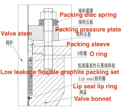
A disc spring permanent-loading clamping mechanism is adopted for the valve stem dynamic seal packing, along with a triple sealing structure consisting of a lip seal ring, low-leakage flexible graphite, and an O-ring, enhancing sealing reliability. This design ensures a reliable and durable dynamic seal for the valve stem in the operating environment. See Figure 1 for the packing triple sealing structure diagram.

Figure 1 The triple sealing structure of the packing

Figure 1 The triple sealing structure of the packing
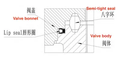
The seal between the valve body and valve bonnet utilizes a lip seal ring (self-tightening seal) and a figure-eight ring (semi-self-tightening seal). The specific structural design is shown in Figure 2 (valve body and valve bonnet sealing structure diagram).

Figure 2 The sealing structure of the valve body and valve bonnet

Figure 2 The sealing structure of the valve body and valve bonnet
Previous: Influence of Anti-Seismic Tooling on the Natural Frequency of Nuclear Power Valves
Next: Manufacturing of High-Pressure Cryogenic Ball Valves for LNG Devices


