Design of a Quality Test Method for Underwater Directional Control Valves
Apr 19, 2025
A set of practical quality test methods for underwater directional control valves (DCVs) was developed based on the API STD 17F-2017 standard. The tests cover external pressure, internal pressure, internal leakage, functional and continuity performance, contaminated fluid circulation, service life, environmental screening, and insulation resistance. For each test, the objectives, standards, and procedures are clearly defined. This method has been reviewed and approved by the Norwegian Classification Society (DNV) and successfully applied to the certification of shallow-water DCV products used in the Bohai oil and gas fields.
The underwater directional control valve (DCV) is a critical component of subsea production systems. It includes various valve types such as subsea safety valves, emergency shut-off valves, isolation valves, check valves, and quick exhaust valves. A DCV typically consists of a pilot valve and a main valve, which work together to control the flow direction of hydraulic fluid, switch the states of hydraulic actuators, and enable the operation of subsea equipment. Currently, leading international directional control valves are primarily developed by companies such as Oceaneering, Aker, and Bifold. For instance, Oceaneering’s 15-series high-pressure DCV operates at depths of up to 4,000 meters with a design pressure of 20,000 psi. Aker's electro-hydraulic directional valves use seawater-corrosion-resistant materials and are rated for pressures up to 15,000 psi. Bifold's products are designed for use with contaminated hydraulic fluids, offering a design depth of 3,000 meters, leakage rates below 0.2 cc/min, a contamination cycle test of 100,000 cycles, and a service life test of one million cycles, far exceeding API requirements. This paper, based on the API standard, systematically investigates qualification testing (QT) and factory acceptance testing (FAT) methods for DCVs. The objective is to break foreign monopolies, establish a test system with independent intellectual property rights, and provide technical support for the design and maintenance of China’s subsea production control systems.
The purpose of the DCV internal pressure test is to verify whether the valve exhibits any external leakage under the specified test pressure. At the start of the test, the actual pressure should not exceed 5% above the test pressure. By the end of the test, the actual pressure must not fall below the test pressure. If any component within the DCV has a lower internal pressure rating than the system's overall internal pressure test requirement, that component must be isolated from the system during the test. The internal pressure test pressure is calculated using the following formula:

Wherein, TP refers to the test pressure and DP to the design pressure. The internal pressure test consists of two stages:
a. Stage 1: Test without pressure-sensitive components
As shown in Figure 1, the pilot valve body, main valve body, and solenoid valve blind plug are first assembled. The hydraulic pump is then raised to 1.5 × 1.05 times the design pressure (to allow a margin for pressure drop), and high-pressure hydraulic oil is injected into the DCV via the main valve’s oil supply port. A stable pressure source is used between the hydraulic pump and the DCV, and any pressure drop can be monitored via a digital pressure gauge to check for external leakage. After holding the pressure for 10 minutes, observe whether the pressure drop exceeds 3% and whether there is any external leakage from the valve body.
b. Stage 2: Test with pressure-sensitive components installed
As shown in Figure 2, the solenoid valve and pressure transmitter are installed in place of the blind plug used in Stage 1. The internal pressure test is then conducted at 1.1 times the design pressure. The hydraulic pump is raised to 1.1 × 1.05 times the design pressure, and pressure is maintained for 10 minutes. Monitor whether the pressure drop exceeds 3%, and inspect for external leakage after pressure relief. Following the test, check the valve core and sleeve holes of the DCV for cracks.
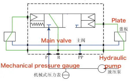
P: main valve oil supply port, R: oil return port, PP: pilot valve oil supply port
Figure 1 DCV Internal Pressure Test – Stage 1
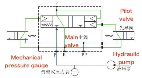
Figure 2 DCV Internal Pressure Test – Stage 2
The purpose of the DCV external pressure test is to verify the sealing integrity of the DCV when exposed to an external silicone oil environment, ensuring that no silicone oil enters the DCV after testing. During the test, the DCV operates within the silicone oil environment of the Subsea Control Module (SCM). If the DCV manufacturer does not possess an SCM, an equivalent testing fixture known as an environmental simulation device must be designed.
First, mount the DCV onto the base of the environmental simulation device (see Figure 3). Fill the device with silicone oil, then use a silicone oil pump to increase the pressure to 1.1 times the design environmental pressure. The pressure ramp-up rate should be no less than 24 bar/min (1 bar = 100 kPa). Once the target pressure is reached, stop pressurization and maintain the pressure for at least 5 minutes before initiating pressure relief. The pressure relief rate should be no less than 36 bar/min. The external pressure test consists of three pressurization-relief cycles. During the high-pressure stage of each cycle, switch the DCV valve position to verify that its control and reset functions operate correctly.
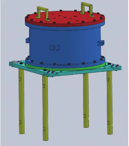
Figure 3 Ring Simulation Device
After the third cycle, the test enters the pressure maintenance stage, during which pressure is maintained for no less than 6 hours (excluding the time taken for the pressure relief and boost cycles). After this period, the pressure is released to atmospheric pressure, the silicone oil is recovered, and any remaining silicone oil on the surface of the DCV is wiped off. The DCV is then removed from the environmental simulation device. Finally, the two pilot valves are disassembled to inspect whether any silicone oil has infiltrated the main valve body.
This test is conducted to verify whether the internal leakage of the DCV complies with the standard requirement of less than 0.2 cc/min. It must be performed at the design pressure of the hydraulic system and while the DCV is in either the control or reset position. Testing begins after the valve has been switched and maintained in position for at least 10 minutes.
Two methods are commonly used:
Method 1: Pressurize the test component and isolate the pressure source, then monitor the pressure drop to assess leakage. This method requires a dedicated fixture that displays pressure drop to evaluate the leakage.
Method 2: Use a stable pressure source to pressurize the component, then collect hydraulic oil through the return port and calculate the leakage based on the collected volume.
Test procedure:
Mount the DCV onto the test bench. Raise the hydraulic power unit to the maximum design pressure, ensuring both the pilot valve and main valve receive the same supply pressure. Switch the DCV to the control position. After the system stabilizes for 10 minutes, collect the hydraulic oil from the return port using a graduated cylinder for 10 minutes, and calculate the leakage rate per minute. Then switch the DCV to the reset position and repeat the same process.
This test is used to verify the control, reset, and valve position holding functions of the DCV. Install the DCV on the test bench, raise the hydraulic power unit to the maximum design pressure, and switch the DCV valve position 10 times, with a 10-minute interval between each operation. Observe the functional performance during each switch. To test the starting pressure, switch the DCV to the control state, open the oil supply pressure relief valve, and record the pressure value at the function port when it suddenly drops to 0 MPa. Repeat the test three times to determine the starting pressure range.
In a hydraulic system with a contamination level of NAS 1638 Class 12, this test verifies whether the internal leakage of the DCV remains below 0.4 cc/min after the specified number of switching cycles has been completed. The test can be conducted in either open or closed mode: in open mode, the hydraulic oil is discharged directly; in closed mode, the hydraulic oil is returned to the tank. A switching operation is performed each time the volume of outflow or return hydraulic oil exceeds 10 cc. The test pressure is equal to the DCV design pressure. The level of oil contamination should be monitored regularly throughout the test. The minimum contamination concentration limits are shown in Table 1.
Table 1 Hydraulic Fluid Contamination Requirements for Circulation Test
|
Test Phase |
Contamination Criteria (particles >14 µm per 100 mL) |
|
Before the test |
Minimum 188,346 |
|
During the test |
Minimum 166,188 |
During the commissioning process, the number of particles larger than 14 μm per 100 mL must be at least 166,188. First, install the DCV on the test bench. The hydraulic power unit should be pressurized to the maximum design pressure, and both the pilot valve and main valve should receive oil supply at this pressure. The DCV is then cycled between the control and reset states. Hydraulic oil samples are taken upstream of the DCV, and the concentration of contaminants is recorded. If the concentration falls below the minimum threshold, the test must be stopped, the test fixture cleaned, and the test restarted. Each restart counts as a new test cycle, and the number of test cycles is incremented accordingly. When the number of switching cycles reaches 200, 500, 1000, 2000, 2500, 2950, and 3000, hydraulic oil is collected from the return oil port using a measuring cylinder. Before each collection, the DCV must remain stable in either the reset or control state for at least 10 minutes. The volume of hydraulic oil collected is then observed to calculate the leakage rate per minute.
The purpose of the DCV life test, conducted under design pressure, is to verify that the design service life of the DCV meets or exceeds the required number of operational cycles in actual applications. The total number of switching cycles must not be less than 10,000. If the equipment does not experience any failure during the test, it is considered to have passed. First, install the DCV on the test bench. Pressurize the hydraulic power unit to the maximum design pressure, ensuring that both the pilot valve and main valve are supplied at this pressure. Alternate the DCV between the control and reset states. At every 10,000 accumulated switching cycles, place the DCV in the control state. After stabilizing for 10 minutes, collect hydraulic oil from the return oil port using a measuring cylinder for 10 minutes. Observe the volume of oil collected and calculate the leakage rate per minute.
The environmental screening test for DCV supporting electronic components is conducted to ensure that the DCV does not suffer any damage or functional degradation during transportation, handling, installation, or operation. The pressure transmitters and solenoid pilot valves are considered supporting electronic components and must undergo separate temperature, shock, and vibration tests. If the manufacturers of the pressure transmitter and solenoid pilot valve can provide valid test certificates, these components may be exempt from testing.
The temperature test must be performed before the vibration test. First, integrate the DCV with the test fixture, place it on the temperature test bench, and secure it in position. Then, maintain the DCV at the highest design temperature for 48 hours. Perform a power-off/power-on test at the beginning of the high-temperature phase. During the insulation period, verify the functional and communication performance of the solenoid pilot valve and pressure transmitter to ensure they are operating normally. Another power-off/power-on test is performed at the end of the insulation period.
Next, conduct a high- and low-temperature cycle test. The DCV is cycled through a temperature range of -18°C to 40°C, with a temperature change rate of 5°C per minute. Each high- and low-temperature phase lasts 30 minutes, for a total of 10 cycles. During the test, the solenoid pilot valve and pressure transmitter must continue to function normally. If a fault occurs during the thermal cycling, it should be repaired promptly, and the cycle test must be restarted. The test is considered passed when 10 consecutive fault-free cycles are completed. After the test, verify the DCV valve position switching function and the functionality of the pressure transmitter.
After the vibration test, the DCV must show no visible damage or deformation, and the solenoid pilot valve and pressure transmitter must pass their functional tests. First, place the integrated DCV on the vibration test bench and secure it firmly. Apply a reciprocating frequency sweep from 5 to 150 Hz along each of the three mutually perpendicular axes. Monitor for resonance with a mechanical amplification factor greater than 10 to determine the sensitive axis. Once identified, apply random vibration to the sensitive axis for 2 hours. After the test, inspect the DCV to ensure that no fastening bolts have loosened.
The impact test applies four shocks in six directions along three mutually perpendicular axes. First, secure the integrated DCV fixture to the impact test bench. Then, apply four shocks in each of the six directions along the three axes, one of which is perpendicular to the plane of the circuit board. Each shock should have an impact level of 10g with a half-sine pulse of 11 ms. After the test, inspect the DCV and its fixture for any damage or deformation. The solenoid pilot valve and pressure transmitter must successfully pass their functional tests.
The standard requirements and procedures for the internal pressure test during the DCV factory acceptance test are specified in Section 1.1. After pressure is released, disassembly of the pilot valve and pressure transmitter is not required, and flaw detection is not necessary. Check for any external leakage at the connections.
First, mount the DCV onto the base of the environmental simulation device. Fill the device with silicone oil until the DCV is fully submerged. Use a silicone oil pump to increase the pressure to 1.1 times the actual operating environmental pressure, with a pressure rise rate of no less than 18 bar/min. Maintain the pressure for 10 minutes, then release the pressure at a rate of no less than 24 bar/min. Observe whether the control and reset functions operate normally. Recover the silicone oil, wipe off any silicone oil from the DCV surface, remove the DCV from the simulation device, and check for any silicone oil infiltration at the connections.
The standard requirements and procedures for the internal leakage test during the DCV factory acceptance test are detailed in Section 1.3.
The standard requirements and procedures for the function and continuity test during the DCV factory acceptance test are detailed in Section 1.4.
The DCV environmental screening test is conducted to verify whether the DCV has potential failures resulting from manufacturing processes or assembly issues. Environmental screening is performed before the delivery of DCV engineering products and includes temperature and vibration tests. The temperature test verifies whether the DCV functions reliably within the design temperature range, while the vibration test helps identify assembly-related problems.
The temperature test must be conducted before the vibration test. First, the integrated DCV test fixture is placed on the temperature test bench and securely fixed. The DCV is subjected to 10 temperature cycles between -18°C and 40°C, with a temperature change rate of 5°C/min and a high/low temperature duration of 30 minutes for each cycle. After the temperature cycling, the DCV is maintained at the highest design temperature for 48 hours. Following the temperature test, the DCV valve position switching function is checked to ensure that internal leakage is less than 0.2 cc/min.
There should be no visible damage or deformation after the vibration test, and both the solenoid pilot valve and pressure transmitter must pass a complete functional test. First, the integrated DCV is placed on the vibration test bench and securely fixed. Random vibration is then applied along the DCV’s highest stress axis. The random vibration should last for 10 minutes, and the vibration spectrum is shown in Figure 4.
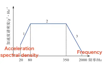
Figure 4 Acceleration Spectral Density Across the Frequency Range
In Figure 4:
From 20 to 80 Hz, the acceleration increases at a rate of 3 dB per octave.
From 80 to 350 Hz, the acceleration spectral density remains constant at 0.04 g²/Hz.
From 350 to 2000 Hz, the acceleration decreases at a rate of 3 dB per octave.
The overall composite excitation level is 6 g. After the vibration test, visually inspect the DCV to ensure that all fastening bolts are secure and there is no loosening.
The purpose of the insulation resistance test is to verify the insulation performance of all electrical components and assemblies of the DCV, including the pressure transmitter and solenoid pilot valve. The test voltage is 50 V, and the reading should be recorded after the voltage has been applied for 60 seconds. The insulation resistance must not be less than 1 GΩ. During the test, the insulation resistance value should remain stable within the 60-second duration, and the test voltage must not exceed the maximum rated voltage of the equipment. Since humidity and temperature can affect the insulation resistance readings, any significant impact must be documented and explained. The recommended insulation resistance (IR) values are listed in Table 2.
Table 2: Recommended Insulation Resistance (IR) Values for Underwater Electrical Distribution
|
Object or Equipment Type |
Recommended IR (GΩ) |
|
Single instrument, single circuit |
≥ 20 |
|
Instrument with jumper (before HV test) |
≥ 10 |
|
Instrument with jumper (after HV test) |
≥ 20 |
|
Jumper with connector |
≥ 10 |
|
Single connector |
≥ 20 |
The author has developed a series of test procedures based on the performance indicators of foreign DCV products, as well as the requirements of underwater production control systems and subsea high-integrity pressure protection systems. These procedures provide both methodology and technical support for DCV factory testing. The paper outlines key points in the DCV testing process and specifies the standard requirements for DCVs and related products. This testing approach verifies the reliability of DCV products and can serve as a reference for factory testing of DCVs in China. Currently, the method has passed review by the Norwegian Classification Society and has been successfully applied during on-site certification of shallow-water subsea directional control valve engineering products in the Bohai oil and gas fields.
Previous: Finite Element Analysis of Titanium Floating Ball Valve Seats

