Application of Ceramic Valves in Calcium Carbide Slurry Production
Jan 27, 2025
Replacing the valves in the slurry pipeline with ceramic valves has significantly reduced valve failure rates and the need for frequent maintenance. This article addresses the challenges and solutions related to the pneumatic valves in the clean water pipeline of the acetylene plant, with a focus on material selection for safe and efficient operation. The acetylene process is used to produce vinyl chloride, where wet acetylene is generated. Calcium carbide, the slurry's primary component, is produced by combining carbon and calcium oxide in a high-temperature furnace. When calcium carbide reacts with water, it forms a slurry primarily consisting of calcium hydroxide and impurities such as water, coke, calcium carbonate, tar, ferrosilicon, and silicon dioxide. The presence of coke, calcium carbonate, and ferrosilicon causes carbide slag to adhere to the internal and external surfaces of equipment and valves, increasing wear. Over time, wear damages the valve sealing surfaces, causing internal leakage and requiring frequent maintenance.
The primary component of carbide slag slurry is calcium hydroxide, which has a limited solubility in water. As the temperature decreases, solid calcium hydroxide particles gradually precipitate, forming a thin, viscous slurry. Additionally, solid impurities from the carbide, such as ferrosilicon, sand, and coke, which do not participate in the reaction, are mixed into the slurry. These impurities contribute to the formation of solid mixtures in stagnant areas, leading to blockages in valves and pipelines. The large particle size and high hardness of the ferrosilicon, sand, and coke increase the risk of valve wear and clogging.
Valves in acetylene plants are typically made from surface-coated or custom metal alloys. However, regulating valves for carbide slag slurry face challenges due to changing flow directions during operation. In these valves, the flow rate is often higher than in the connected pipeline, exposing the valve core to harsh conditions that accelerate wear, further worsened by the slurry's corrosive nature. In some instances, valves may remain open or closed for extended periods, sometimes for a week or longer, without being actuated. Alternatively, some valves may require frequent operation, opening and closing multiple times per hour. While frequent use reduces the likelihood of failure from scaling or sediment buildup, it increases wear susceptibility. The calcium carbide slag slurry also contains large quantities of unreacted ferrite and calcium carbide blocks, which may cause significant damage to the valve core, complicating repairs and leading to internal leakage. Over time, slurry corrosion reduces the valve core's flexibility, making it difficult to rotate the valve and delaying emergency closure. This could result in a risk of pressure release. As a result, valves made from these materials typically have a shorter service life.
Silicon nitride, a key component in ceramic materials, is an ultra-hard compound known for its low density, lubricity, wear resistance, and exceptional corrosion resistance. In recent years, it has seen widespread use in the manufacturing of valve internals. Ceramic ball valves, in particular, are the most commonly used type in industrial applications. The self-lubricating properties of ceramic materials provide superior sealing and enhanced wear resistance, addressing the limitations of metal sealing surfaces, which are prone to leakage and corrosion. Ceramic materials offer distinct advantages in applications involving abrasive or both particulate and corrosive media. They are well-suited to meet the stringent demands of industrial processes.
Table 1 Chemical Composition of Ceramic Materials
|
Material |
Chemical Composition |
Percentage (%) |
|
Silicon Nitride (Si₃N₄) |
Silicon (Si), Nitrogen (N) |
Si: 66.7%, N: 33.3% |
|
Alumina (Al₂O₃) |
Aluminum (Al), Oxygen (O) |
Al: 52.9%, O: 47.1% |
|
Zirconia (ZrO₂) |
Zirconium (Zr), Oxygen (O) |
Zr: 93.2%, O: 6.8% |
|
Boron Carbide (B₄C) |
Boron (B), Carbon (C) |
B: 80.2%, C: 19.8% |
|
Magnesia (MgO) |
Magnesium (Mg), Oxygen (O) |
Mg: 60.3%, O: 39.7% |
|
Titania (TiO₂) |
Titanium (Ti), Oxygen (O) |
Ti: 59.9%, O: 40.1% |
|
Silica (SiO₂) |
Silicon (Si), Oxygen (O) |
Si: 46.7%, O: 53.3% |
Table 2 Physical Properties of Ceramic Materials
|
Property |
Silicon Nitride (Si₃N₄) |
Alumina (Al₂O₃) |
Zirconia (ZrO₂) |
Boron Carbide (B₄C) |
Magnesia (MgO) |
Titania (TiO₂) |
Silica (SiO₂) |
|
Density (g/cm³) |
3.2 – 3.3 |
3.90 |
5.65 |
2.52 |
3.58 |
4.23 |
2.20 |
|
Hardness (Vickers, HV) |
1,800 – 2,200 |
1,000 – 1,500 |
1,200 – 1,400 |
2,400 |
1,200 |
1,300 |
1,500 |
|
Flexural Strength (MPa) |
800 – 1,200 |
300 – 500 |
800 – 1,200 |
1,800 |
700 |
1,000 |
90 |
|
Thermal Conductivity (W/m·K) |
30 – 35 |
20 – 30 |
2.0 – 3.0 |
30 |
30 – 40 |
7 – 12 |
1.3 – 1.7 |
|
Coefficient of Thermal Expansion (10⁻⁶/K) |
2.5 – 3.5 |
6.5 – 8.0 |
10.5 – 11.0 |
4.5 |
13.1 |
8.0 – 10.0 |
0.5 |
|
Porosity (%) |
< 2 |
< 0.1 |
< 0.1 |
< 1 |
< 1 |
< 1 |
5 – 10 |
|
Fracture Toughness (MPa·m½) |
6 – 8 |
3.5 – 5.0 |
6 – 7 |
4.5 |
1.5 |
4.0 |
0.3 |
|
Maximum Service Temperature (°C) |
1,600 – 1,700 |
1,800 – 2,000 |
2,300 – 2,400 |
2,500 |
2,000 |
1,800 |
1,200 |
Table 3 Mechanical Properties of Ceramic Materials
|
Property |
Silicon Nitride (Si₃N₄) |
Alumina (Al₂O₃) |
Zirconia (ZrO₂) |
Boron Carbide (B₄C) |
Magnesia (MgO) |
Titania (TiO₂) |
Silica (SiO₂) |
|
Compressive Strength (MPa) |
1,200 – 2,500 |
1,000 – 2,000 |
2,500 – 3,000 |
2,500 – 3,000 |
250 |
300 – 400 |
2,000 |
|
Tensile Strength (MPa) |
300 – 800 |
200 – 400 |
500 – 1,000 |
500 – 700 |
100 |
250 – 300 |
50 – 100 |
|
Young's Modulus (GPa) |
300 – 330 |
300 – 400 |
200 – 220 |
450 – 500 |
150 – 170 |
120 – 150 |
60 – 70 |
|
Poisson's Ratio |
0.26 – 0.30 |
0.22 – 0.30 |
0.28 – 0.31 |
0.18 – 0.21 |
0.22 |
0.30 |
0.17 |
|
Hardness (Mohs Scale) |
9.0 – 9.5 |
9.0 – 9.5 |
8.0 – 8.5 |
9.5 |
5.5 – 6.0 |
6.0 – 6.5 |
6.5 – 7.0 |
|
Impact Toughness (MPa·m½) |
3.5 – 5.0 |
2.5 – 4.0 |
3.0 – 4.0 |
2.5 – 4.0 |
1.0 – 2.0 |
1.5 – 3.0 |
0.5 – 1.0 |
|
Fatigue Strength (MPa) |
300 – 600 |
150 – 250 |
200 – 400 |
300 – 400 |
50 – 100 |
150 – 200 |
20 – 50 |
|
Creep Resistance (MPa) |
200 – 300 |
150 – 200 |
100 – 150 |
250 – 350 |
50 – 70 |
100 – 150 |
20 – 40 |
The chemical composition of the ceramic materials is provided in Table 1, the physical properties are outlined in Table 2, the mechanical parameters are listed in Table 3, and the corrosion resistance data is presented in Table 4.
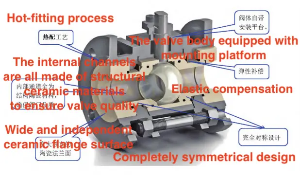
The ceramic ball valve integrates the advantages of structural ceramics and ball valves, significantly broadening their range of applications. It functions not only as a shut-off valve but also as a control valve. The advanced design of the ceramic ball valve simplifies installation, enhances versatility, and improves reliability. It is also fully compatible with all industry-standard ball valve specifications. The schematic diagram is provided in Figure 1.

Figure 1 Ceramic valves
- The valve features a three-piece, fully symmetrical design that eliminates flow direction restrictions and allows installation in any orientation, thereby extending its service life.
- The valve's primary sealing mechanism employs a ceramic-to-ceramic hard seal, with all ceramic components constructed from wear-resistant materials. This maximizes the high hardness of structural ceramics, enhancing the valve's wear resistance and ensuring stable, reliable performance. The ball core achieves a roundness of up to 1 μm and a surface roughness of 0.2 μm. The valve seat incorporates a curved surface sealing design, enhancing the sealing pressure ratio and ensuring the stability and reliability of the seal.
- The floating structure ensures that, during operation, the ball core is pressed against the ceramic valve seat by pipeline pressure, maintaining a tight seal between the ball core and valve seat.
- The ball core is composed entirely of ceramic material, significantly enhancing the valve's wear resistance.
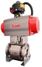
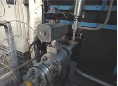
During the slurry treatment process in the acetylene unit, the slurry buffer tank level control valve (2LV-1215) initially did not incorporate a ceramic valve. After approximately six months of operation, the liquid level in the process slurry buffer tank became difficult to regulate. Inspection revealed that the valve had undergone erosion and wear. In 2019, after analyzing valve failures and operational conditions, the decision was made to replace the metal body of the original pneumatic valve with a ceramic valve body. The ceramic pneumatic valve was installed during the scheduled overhaul in July. A follow-up inspection in 2020 found no signs of erosion, wear, or scaling, and the pneumatic valve had operated without failure since installation. Based on the performance analysis of the acetylene unit, the decision was made in 2020 to replace the feed valve, squeeze valve, withdrawal valve, and back-blowing valve on the cement plant’s filter press with ceramic valves. This change was implemented under the same operating conditions. Since the July 2020 overhaul of Filter Press No. 3, there have been no occurrences of valve leakage, scaling-related jamming, or other failures, leading to a significant reduction in valve failure rates.
Based on the performance of ceramic valves, our company has systematically replaced pneumatic valves on the slurry pipeline with ceramic valves. This change has significantly reduced the frequency of valve maintenance and replacement, improved the safety and stability of supporting equipment, reduced labor intensity, minimized equipment maintenance requirements, and resulted in procurement cost savings.
Previous: State Monitoring and Fault Diagnosis of Electric Valves
Next: Simulation Analysis of Cryogenic Ball Valve Based on Thermo-Solid Coupling


